High power incoherent light source with laser array

a laser array and high-power technology, applied in the field of incoherent light sources, can solve the problems of many maintenance and safety concerns, large and inefficient light sources, and significant disadvantages of light sources

Inactive Publication Date: 2002-09-12
BALL SEMICON
View PDF7 Cites 172 Cited by
  • Summary
  • Abstract
  • Description
  • Claims
  • Application Information

AI Technical Summary

Benefits of technology

0008] A technical advance is provided by a novel light source and method for projecting light onto a subject. In one embodiment, the light source comprises a diode array for producing one or more individual laser lights, where the diode array includes at least one diode. The light source also includes a combiner for combi

Problems solved by technology

However, these light sources have significant disadvantages.
For one, they are very expensive.
Also, they are large and inefficient.
Further, there are many maintenance and safety concerns in these light sources.
Some

Method used


Image

  • High power incoherent light source with laser array
  • High power incoherent light source with laser array
  • High power incoherent light source with laser array

Examples


Embodiment Construction

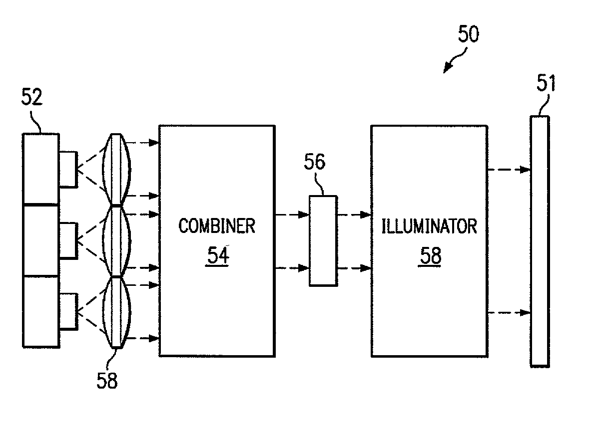
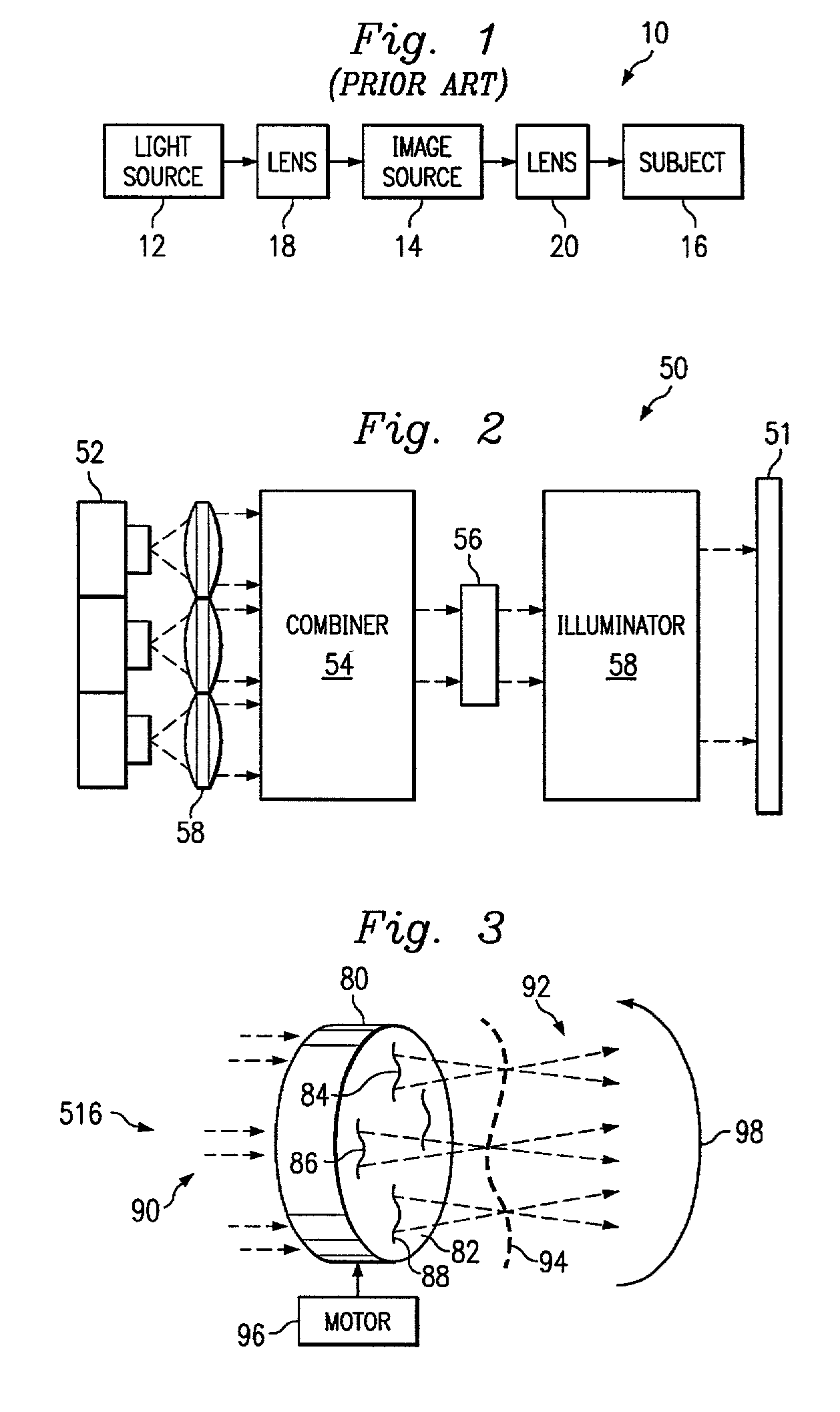
[0018] The present disclosure relates to light sources, and more particularly, to a high power incoherent light source using an array of solid-state lasers. The light source can be used in imaging systems, such as are discussed above, as well as other similar applications. It is understood, however, that the following disclosure provides many different embodiments, or examples, for implementing different features of the invention. Specific examples of components and arrangements are described below to simplify the present disclosure. These are, of course, merely examples and are not intended to be limiting. In addition, the present disclosure may repeat reference numerals and / or letters in the various examples. This repetition is for the purpose of simplicity and clarity and does not in itself dictate a relationship between the various embodiments and / or configurations discussed.

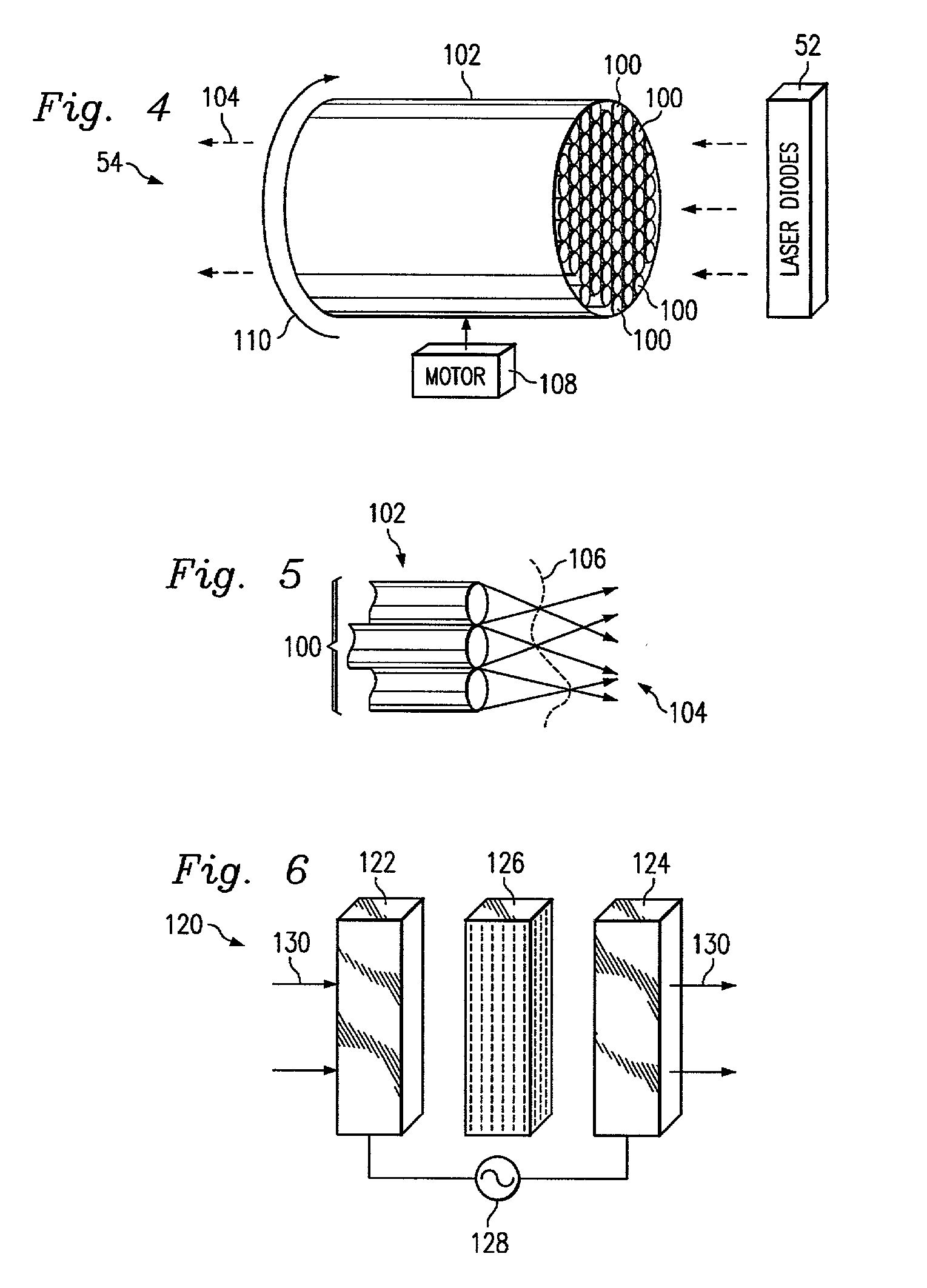
[0019] Solidlasers, such as an ultra violet (UV) laser diode, have many merits, including high energy eff...


PUM


Abstract

A high power light source is provided. The light source includes one or more diodes that may produce relatively coherent light of a desired intensity. The diodes may be pulsed to provide light as desired. The light projected by the diodes passes through a combiner, which combines the light from the different diodes and passes the combined light to an incoherence apparatus. The incoherence apparatus may include a rotating surface relief phase device such as an optical hologram, a computer generated hologram, or a diffractive optical element with random phase modulation. The incoherence apparatus may include a rotating fiber conduit comprising a plurality of multifiber cores. The incoherence apparatus renders the combined light incoherent and passes it to an illuminator apparatus that focuses the incoherent combined light onto an image plane.

Description

CROSS REFERENCE TO RELATED APPLICATIONS[0001] This application claims the benefit of U.S. Provisional Application No. 60 / 274,371, filed on Mar. 8, 2001.BACKGROUND[0002] This disclosure relates generally to incoherent light sources, such as can be used in display systems and / or photolithography exposure systems.[0003] In conventional display and photolithography exposure systems, an image source is required for exposing an image onto a subject. With photolithography systems, the subject may be a photo resist coated semiconductor wafer for making integrated circuits, a metal substrate for making etched lead frames, or a conductive plate for making printed circuit boards. With display systems, the subject may be a display screen, such as is used by a projector. For the sake of the present discussion, display systems and exposure systems will be collectively discussed as "imaging systems," unless otherwise noted.[0004] With reference now to FIG. 1, a conventional imaging system 10 inclu...

Claims


Application Information

Patent Timeline
IPC IPC(8): G02B5/32G02B6/42G03F7/20H04N9/31
CPCG02B5/32G02B6/42G02B6/4206G02B6/425G02B27/48G03F7/70025G03F7/70041G03F7/7005H04N9/3129
Inventor ZHAI, JINHUIMEI, WENHUICHAN, KIN FOONG
Owner BALL SEMICON
Why Eureka
Try Eureka