DC-DC converter and bi-directional DC-DC converter and method of controlling the same

a dc-dc converter and converter technology, applied in the direction of electric variable regulation, process and machine control, instruments, etc., can solve the problems of increasing the switching frequency in proportion to the switching frequency, reducing the switching loss, and increasing the switching frequency is not suitabl

Inactive Publication Date: 2002-09-12
NISSIN ELECTRIC CO LTD
View PDF0 Cites 88 Cited by
  • Summary
  • Abstract
  • Description
  • Claims
  • Application Information

AI Technical Summary

Benefits of technology

0033] In this manner, even in the case where fault such as overvoltage, overcurrent or overtemperature, occurs in the first or second converter circuit portions, the fault state can be detected by the fault detecting units so that the first or second converter circuit portions can be stopped on the basis of gate blocking signals output from the fault judging circuit. Hence, the self-protecting function of the DC-DC converter can be fulfilled.

Problems solved by technology

As the switching frequency increases, however, the switching loss increases in proportion to the switching frequency.
Hence, to increase the switching frequency is not suitable means for reduction of the switching loss.
Therefore, use of a high withstand voltage MOS-FET brings exponential increase of the conduction loss.
Accordingly, this causes reducing of efficiency of the DC-DC converter.
If such fluctuation in the output voltage V appears, stable electric power source to a load can be hardly performed.
However, because the prior-art DC-DC converter can do nothing but electric power conversion from the primary side to the secondary side, the DC-DC converter was difficult to be applied to the purpose of electric power conversion from the secondary side to the primary side.

Method used


Image

  • DC-DC converter and bi-directional DC-DC converter and method of controlling the same
  • DC-DC converter and bi-directional DC-DC converter and method of controlling the same
  • DC-DC converter and bi-directional DC-DC converter and method of controlling the same

Examples


first embodiment

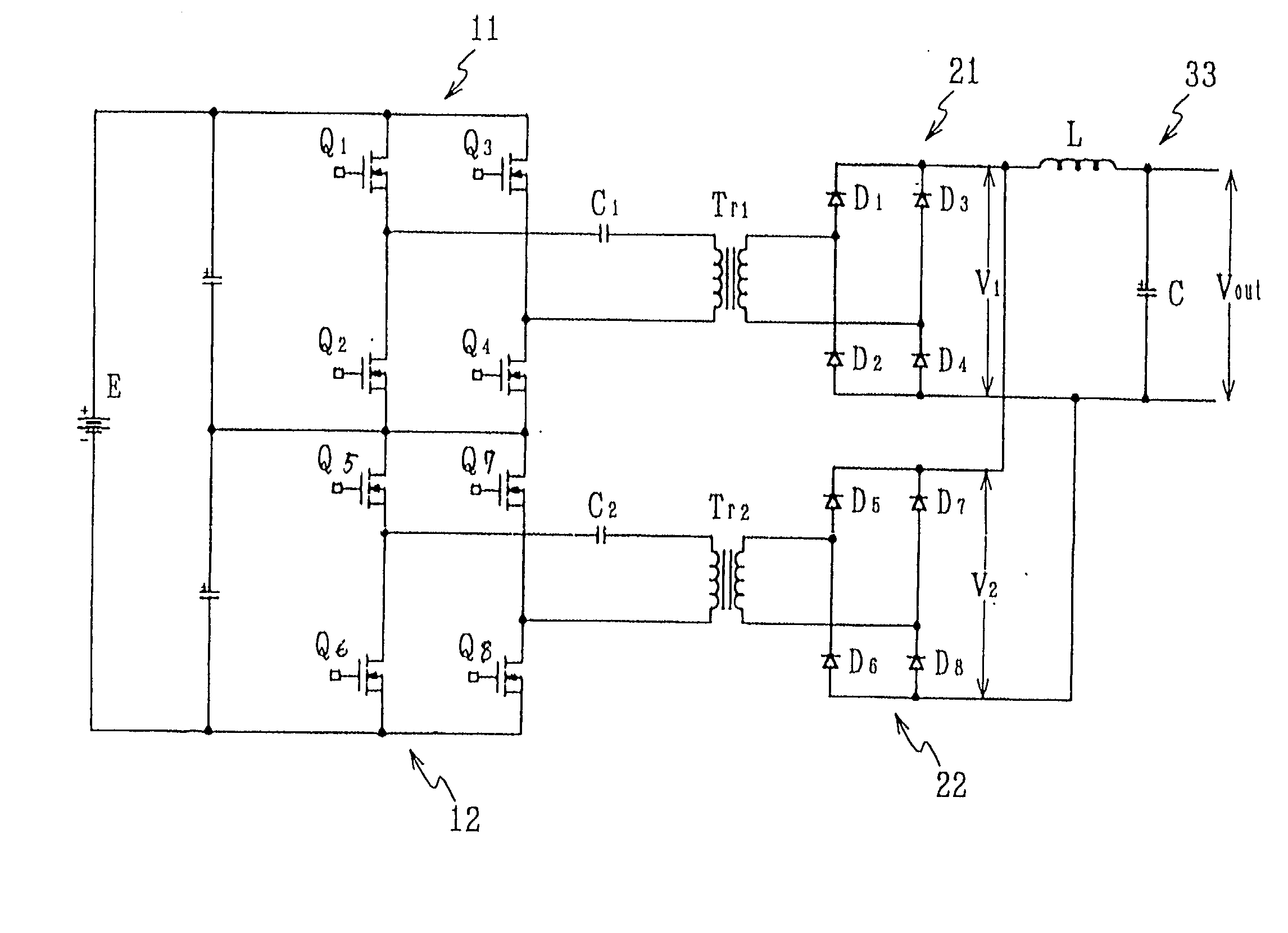
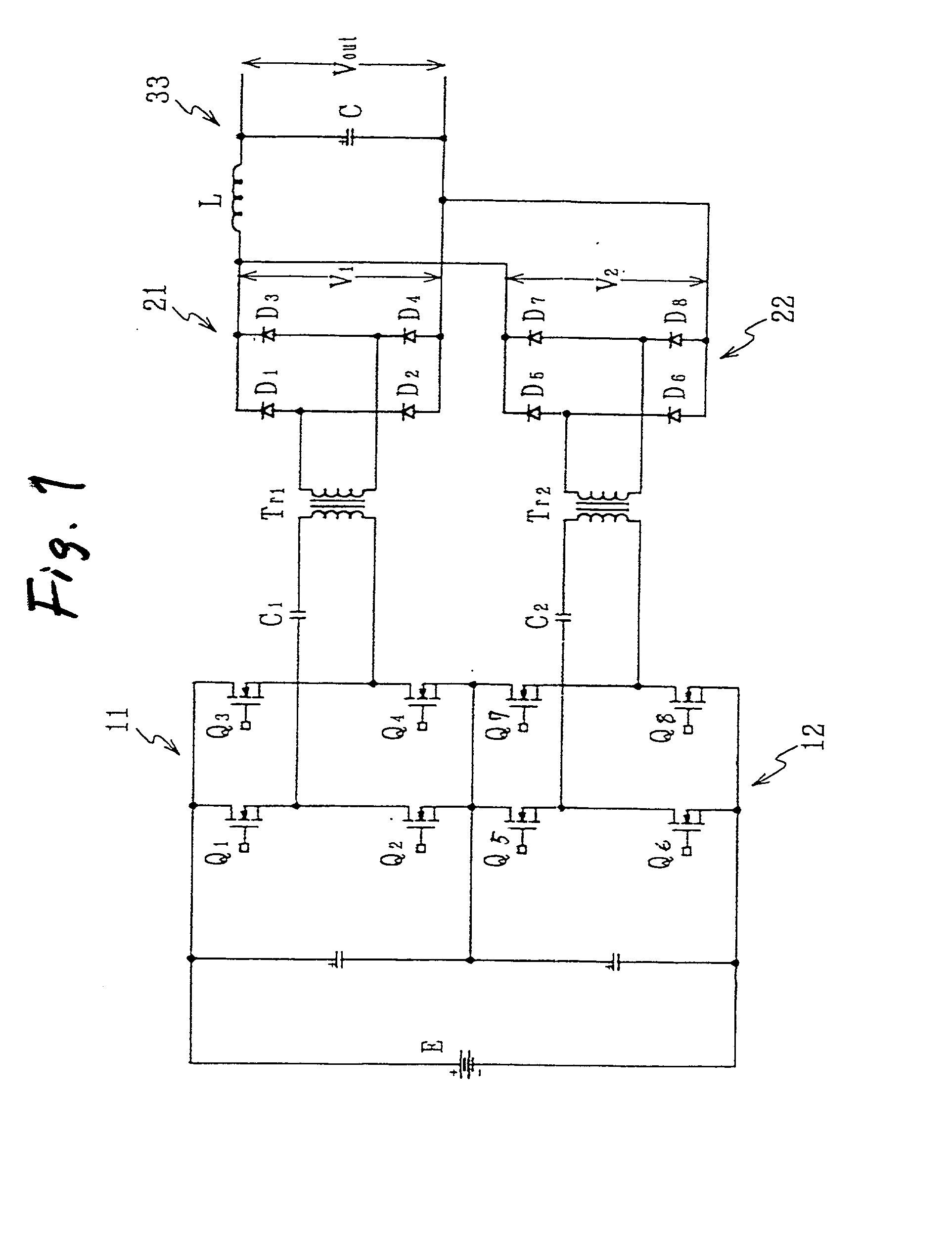
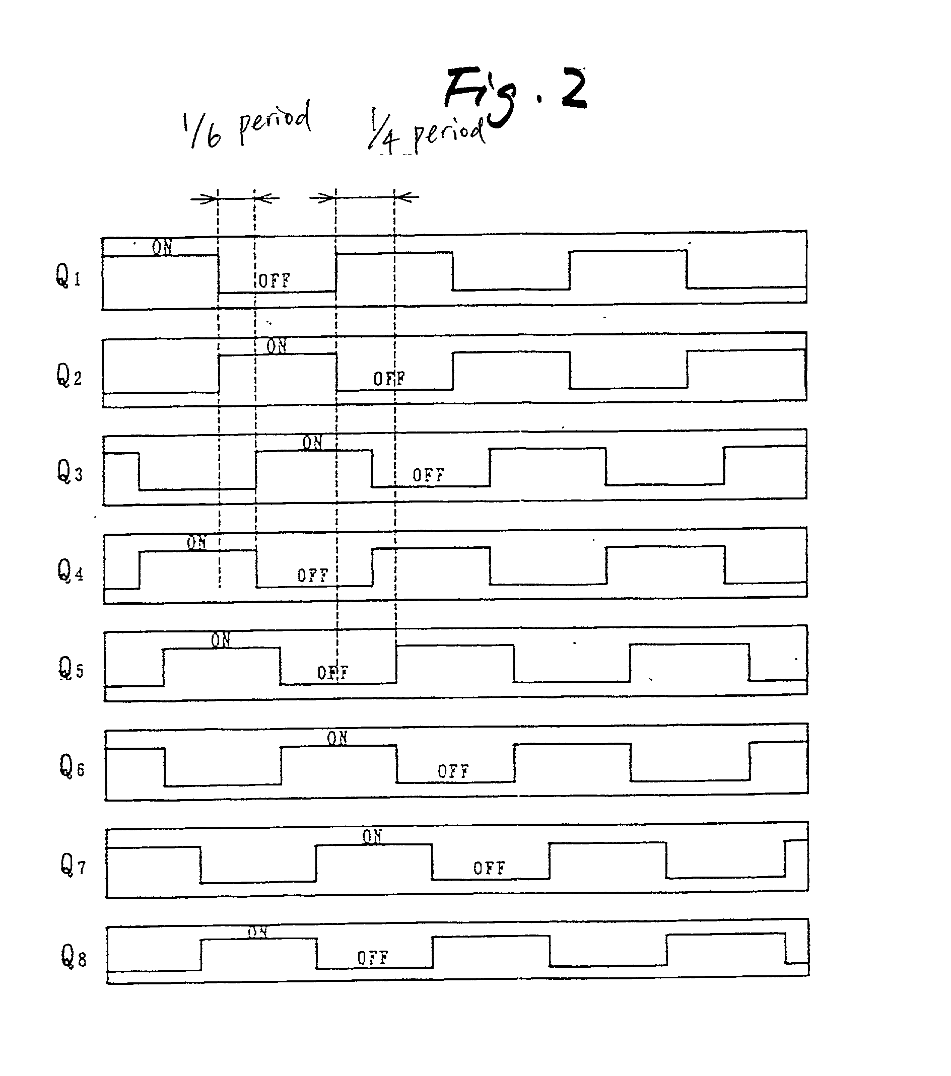
[0061] Embodiments of a DC-DC converter and a bi-directional DC-DC converter according to the invention will be described below in detail. FIG. 1 is a circuit diagram of the DC-DC converter according to the invention. FIG. 2 is a timing chart of gate signals for turning on / off respective switching elements Q.sub.1 to Q.sub.8 in the DC-DC converter. FIG. 3 is a waveform chart of output voltages V.sub.1 and V.sub.2 of rectifier circuit portions 21 and 22, primary voltages of transformers Tr.sub.1 and Tr.sub.2 and drain-source voltages V.sub.ds and drain currents I.sub.d of the respective switching elements Q.sub.1 to Q.sub.8.

[0062] In the first embodiment, the DC-DC converter has n sets (for example, two sets) of converter circuit portions 11 and 12, two transformers Tr.sub.1 and Tr.sub.2, two sets of rectifier circuit portions 21 and 22, and an LC smoothing circuit 33. The two sets of converter circuit portions 11 and 12 respectively include two pairs of switching elements Q.sub.1, Q...

fourth embodiment

[0079] FIG. 7 is a circuit diagram of the DC-DC converter according to the invention. FIG. 8 is a timing chart of gate signals Pg.sub.1 to Pg.sub.4 and Pg.sub.5 to Pg.sub.8 for turning on / off respective switching elements Q.sub.1 to Q.sub.4 and Q.sub.5 to Q.sub.8 in the DC-DC converter. FIG. 9 is a waveform chart of output voltages V.sub.1 and V.sub.2 of rectifier circuit portions 121 and 122, primary voltages of transformers Tr.sub.1 and Tr.sub.2 and drain-source voltages Vds and drain currents Id of the respective switching elements Q.sub.1 to Q.sub.4 and Q.sub.5 to Q.sub.8.

[0080] In this embodiment, the DC-DC converter has a main circuit 110 including n sets (for example, two sets) of converter circuit portions 111 and 112, two transformers Tr.sub.1 and Tr.sub.2, two sets of rectifier circuit portions 121 and 122, and a smoothing circuit portion LoCo. The two sets of converter circuit portions 111 and 112 respectively include two pairs of switching elements Q.sub.1, Q.sub.4 and Q...

fifth embodiment

[0093] FIG. 13 shows a voltage compensating portion for the purpose of compensating the fluctuation (abatement) of the output voltage Vo in accordance with the fluctuation of the input voltage of the DC power source Ed in the DC-DC converter of the The voltage compensating portion includes tap changing circuits 161 and 162 which are provided between the transformers Tr.sub.1, Tr.sub.2 and the rectifier circuit portions 121, 122 in the main circuit 110 for changing taps in the secondary windings of the transformers Tr.sub.1 and Tr.sub.2 respectively.

[0094] In the control portion 151, the output voltage Vo of the rectifier circuit portions 121 and 122 in the main circuit 110 is detected by the voltage detecting unit 150. As shown in FIG. 14, the output voltage Vo detected thus is compared with the instructed output voltage value Vo.sup.ref which is set in advance. Error between the output voltage Vo and the instructed output voltage value Vo.sup.ref as a result of the comparison is a...


PUM


Abstract

A DC-DC converter has converter circuit portions 11 and 12, transformers Tr.sub.1 and T r.sub.2, and rectifier circuit portions 21 and 22. Two sets of converter circuit portions 11 and 12 respectively include two pairs of switching elements Q.sub.1 to Q.sub.4, and two pairs of switching elements Q.sub.5 to Q.sub.8 connected in full bridge configuration, series capacitors C.sub.1 and C.sub.2 are inserted and connected between the converter circuit portions 11 and 12 and the transformers Tr.sub.1 and Tr.sub.2 respectively. The switching phase of one switching element Q.sub.4 or Q.sub.8 is shifted by a 1/3n period from the switching phase of the other switching element Q.sub.1 or Q.sub.5 in the pair of switching elements. The switching phases of corresponding switching elements Q.sub.1 and Q.sub.5 in the converter circuit portions 11 and 12 are shifted by a 1/2n period from each other.

Description

BACKGROUND OF THE INVENTION[0001] 1. Field of the Invention[0002] The present invention relates to a DC-DC converter and a bi-directional DC-DC converter, and a method of controlling the DC-DC converter or the bi-directional DC-DC converter. More particularly, the present invention relates to a DC-DC converter used in a DC power source circuit for converting a power source voltage of a DC power source into a different DC voltage.[0003] 2. Description of the Related Art[0004] For example, FIG. 23 shows an example of a prior- art DC-DC converter used in a DC power source circuit. FIG. 24 is a timing chart showing gate signals G for turning on / off respective switching elements Q.sub.1 to Q.sub.4 in the DC-DC converter.[0005] The DC-DC converter shown in FIG. 23 has a converter circuit portion 1, a transformer Tr, a rectifier circuit 2, and an LC smoothing circuit 3. The converter circuit portion 1 includes two pairs of switching elements Q.sub.1, Q.sub.4 and Q.sub.2, Q.sub.3 (MOS-FETs)...

Claims


Application Information

Patent Timeline
Patent Type & Authority Applications(United States)
IPC IPC(8): H02M3/335
CPCH02M3/33569H02M3/33584H02M2001/0074H02M1/0074H02M3/33573H02M3/33571
Inventor MATSUKAWA, MITSURUKURIO, NOBUHIRONAKAGAKI, HITOSHIHASEBE, TAKAYA
Owner NISSIN ELECTRIC CO LTD
Why Eureka
Try Eureka