Multi-functional AC/DC converter

a converter and multi-functional technology, applied in the direction of electric vehicles, electric power, transportation and packaging, etc., can solve the problems of tru output voltage not enabling a constant potential or constant current charging mode, neither limiting the current flowing into the battery, and tru has been considered unsuitable for charging batteries, etc., to achieve and efficient charging of the battery connected to the bus

Inactive Publication Date: 2002-09-12
HONEYWELL INT INC
View PDF0 Cites 31 Cited by
  • Summary
  • Abstract
  • Description
  • Claims
  • Application Information

AI Technical Summary

Benefits of technology

0009] The present invention addresses these drawbacks of conventional power system designs by providing a multi-functional AC to DC converter that controls AC to DC conversion as a function of at least one characteristic of a battery connected to a DC power bus, such that the voltage output by the converter to the DC power bus is varied to efficiently charge the battery while providing power for the bus connected loads. In one implementation of the present invention, a multi-functional AC to DC converter also adjusts the voltage output to the DC power bus based on a starting condition of an auxiliary power unit ("APU") so that the supplied voltage is suitable for starting the APU. The present invention is suitable for implementation in an aircraft power system to maintain the voltage output within the compliance range of the DC power bus (e.g., between 27.5 and 29.5 Vdc) while adjusting the output voltage to efficiently charge a battery connected to the bus and / or start an APU connected to the bus.
0010] In one embodiment of the present invention, a multifunctional AC to DC converter includes a power control unit that monitors the current level drawn by a recharging battery and controls the voltage output by the AC to DC conversion circuitry based on the charging state of the battery. In a first power control stage, in which the battery is completely or nearly discharged, the power control unit controls the output voltage to a relatively low level (within the compliance range of the power system) to prevent the battery from drawing an uncontrolled or excessive amount of current. As the battery charges, and its internal impedance increases, the power control unit allows the output voltage to increase, thereby maintaining the current flowing to the battery at an adequate level for efficiently charging the battery. When the output voltage reaches a threshold level, the power control unit initiates a second control stage to maintain the output voltage constant at the elevated level (e.g., near the upper compliance limit of the DC power bus) so that the battery continues to charge, albeit at continually decreasing current. During this second power control stage, the power control unit in one implementation of the present invention controls output voltage as a function of battery temperature so that the output voltage is lower for higher battery temperatures and higher for lower battery temperatures. This temperature compensation improves the efficiency of the battery charging process. When the current drawn by the battery drops below a threshold level (e.g., indicating that the battery is about 80% percent recharged), the power control unit initiates a third power control stage to lower the output voltage to a nominal regulated level (e.g., 28 Vdc in an aircraft DC bus implementation) to trickle charge the battery (i.e., achieve constant potential trickle charge mode). This third power control stage prevents electrolyte loss during trickle charge.
0011] By incorporating multiple functions in a single unit, the AC to DC converter of the present invention improves reliability because additional Line Replaceable Units ("LRUs") and associated switching devices are not required to connect / disconnect the charging battery to / from the DC power bus and requires less control and power wiring. Furthermore, because the recharging battery may be continuously connected to the DC power bus, the present invention enables No-Break-Power-Transfers (NBPT) in the DC subsystem during AC power interrupts or other system failures and reduces DC system weight and cost as compared to a system requiring a separate battery charger.

Problems solved by technology

Due to the varying nature of its output voltage, the TRU has been considered unsuitable for charging batteries that are relied on for backup / auxiliary power supply.
Specifically, the varying nature of the TRU output voltage does not enable a constant potential or constant current charging mode.
Although such a DC generator is suitable for charging batteries at constant potential, this approach can neither limit the current flowing into the battery at the beginning of the starting cycle nor compensate for temperature variations, which strongly influence the battery State of Charge ("SOC").
Also, by not controlling the amount of trickle charge, the DC generator causes the battery to lose electrolytes over time.
The RTRU can charge batteries at constant potential, but can neither limit the current flowing into the battery nor compensate for temperature variations.
Also, by not controlling the amount of trickle charge, the RTRU causes the battery to lose electrolytes over time.
This requires special power bus arrangements and restricts the use of the battery as a bus presence, thereby affecting DC power system flexibility and quality.

Method used


Image

  • Multi-functional AC/DC converter
  • Multi-functional AC/DC converter
  • Multi-functional AC/DC converter

Examples


Embodiment Construction

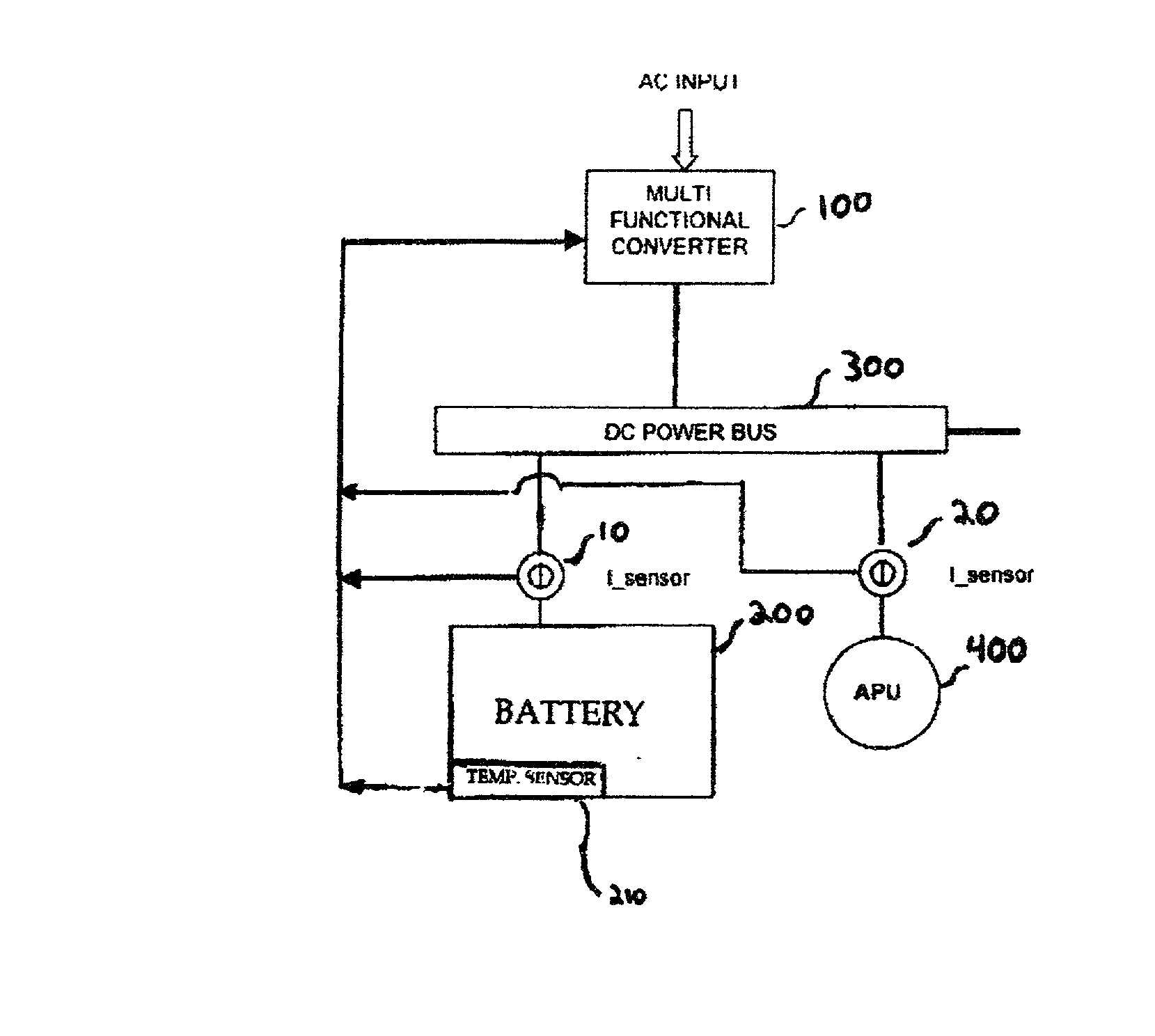
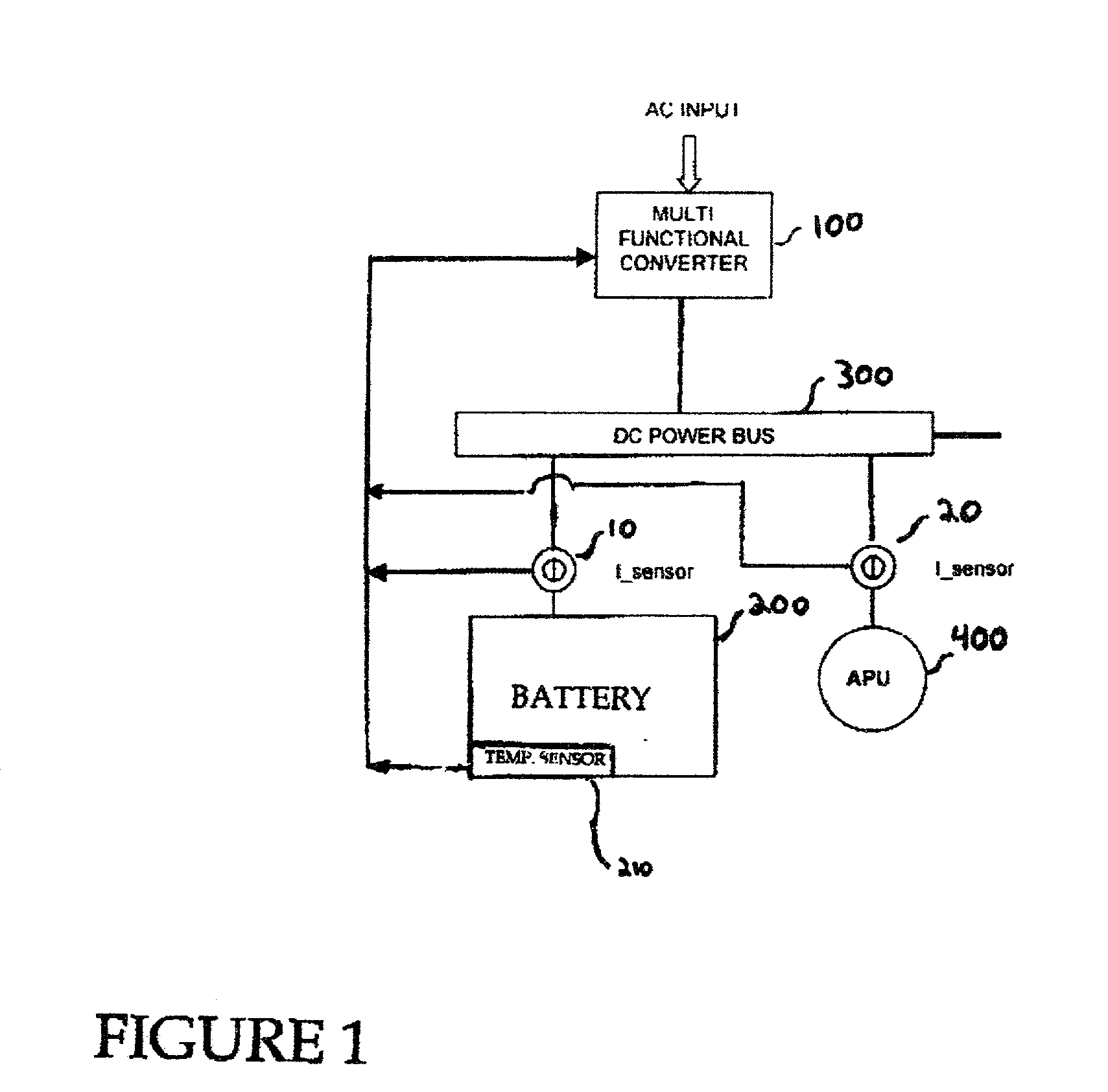
[0017] FIG. 1 illustrates an exemplary implementation of a multifunctional AC to DC converter and its integration into a typical aerospace DC Subsystem according to the present invention. In the exemplary implementation shown in FIG. 1, a multi-functional converter 100, a battery 200, and an auxiliary power unit 400 are connected to a DC power bus 300, which may be one of multiple DC power buses of an aircraft power subsystem. It should be readily apparent that various electrical loads and other elements may be connected to the DC power bus 300. The multi-functional converter 100 receives an AC input (e.g., 115 or 230 Vac) and outputs a voltage that is regulated in accordance with principles of the present invention discussed in detail below. A battery current sensor 10 is provided between the DC power bus 300 and the battery 200 to monitor current flow to the battery 200. Likewise, an APU current sensor 20 is provided between the DC power bus 300 and the APU 400 to monitor current ...


PUM


Abstract

A multi-functional AC to DC converter (100) controls AC to DC conversion as a function of at least one characteristic of a battery (200) connected to a DC power bus (300), such that the voltage output by the converter (100) to the DC power bus (300) is varied to efficiently charge the battery (200). In one implementation of the present invention, a multi-functional AC to DC converter (100) also adjusts the voltage output to the DC power bus based on a starting condition of an auxiliary power unit (400) so that the supplied voltage is suitable for starting the APU (400). The present invention is suitable for implementation in an aircraft power system to maintain the voltage output within the compliance range of the DC power bus (e.g., between 27.5 and 29 Vdc) while adjusting the output voltage to efficiently charge a battery (200) connected to the bus (300) and/or start an APU (400) connected to the bus (300).

Description

RELATED APPLICATION[0001] This application claims priority under 35 U.S.C. .sctn.119(e) of U.S. Provisional Application No. 60 / 250,390 filed on Nov. 30, 2000, the entire contents of which are herein incorporated by reference.BACKGROUND OF THE INVENTION[0002] 1. Field of the Invention[0003] This invention relates to an AC to DC converter of an electrical power system.[0004] 2. Description of Related Art[0005] A conventional power system design includes a Transformer Rectifier Unit ("TRU") as a main DC power source, the output voltage of which varies with applied load. Due to the varying nature of its output voltage, the TRU has been considered unsuitable for charging batteries that are relied on for backup / auxiliary power supply. Specifically, the varying nature of the TRU output voltage does not enable a constant potential or constant current charging mode. To address this drawback, some systems use an ON / OFF device to connect and disconnect the battery from the TRU bus to improve c...

Claims


Application Information

Patent Timeline
Patent Type & Authority Applications(United States)
IPC IPC(8): H02J7/04
CPCH02J7/04H02J2310/44H02J7/007
Inventor LAZAROVICH, DAVID
Owner HONEYWELL INT INC
Why Eureka
Try Eureka