
Method of symbol timing synchronization in communication systems

Active Publication Date: 2002-09-12
QUALCOMM INC
View PDF12 Cites 70 Cited by
  • Summary
  • Abstract
  • Description
  • Claims
  • Application Information

AI Technical Summary

Benefits of technology

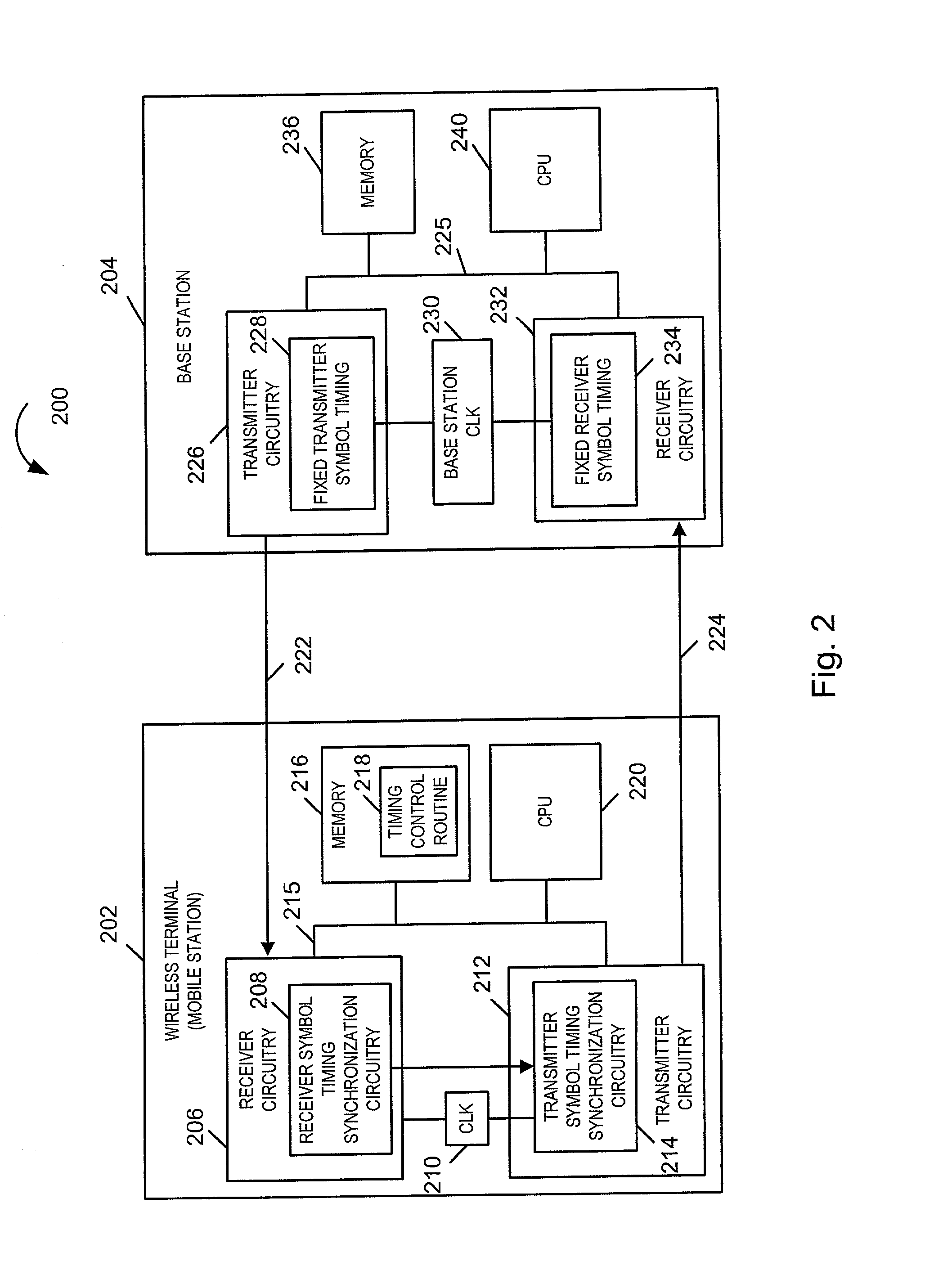
[0029] By adjusting transmitter symbol timing of mobile wireless devices in the above described manner as a function of receiver timing adjustments, the need to adjust base station receiver symbol timing to match that of a particular wireless communication device's transmitter symbol timing is reduced or avoided. In addition, the need to transmit transmitter symbol timing correction signals to individual mobile wireless devices, instructing the specific individual wireless device how to adjust its transmitter timing, is reduced or avoided. Accordingly, the methods and apparatus of the present invention can facilitate the efficient use of the available communications bandwidth.

Problems solved by technology

However, due to cost considerations, wireless terminals, e.g., mobile telephones and / or other mobile communications devices, often use inexpensive clocks.
In many cases, such inexpensive clocks are less accurate than the clocks used in the base stations with which the mobile stations interact.
However, in other systems, the prior art synchronization method does not work effectively.
As different wireless terminals are likely to have different and time varying transmitter timing, it is not feasible to adjust the base station receiver timing as a slave to the transmitter timing of the numerous individual wireless terminals with which a base station receiver may interact.
Hence, the prior art synchronization system does not work effectively in OFDM multiple access systems.

Method used


Image

  • Method of symbol timing synchronization in communication systems
  • Method of symbol timing synchronization in communication systems
  • Method of symbol timing synchronization in communication systems

Examples


Embodiment Construction

[0030] The present invention is applicable to a wide range of digital communications systems, point-to-point or multiple access, where a first communication device communicates with a second communication device.

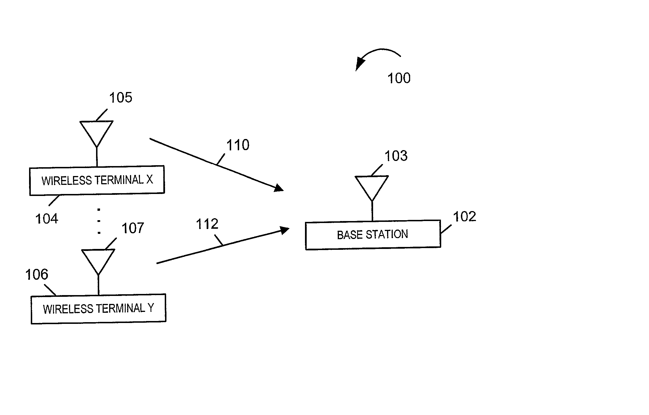
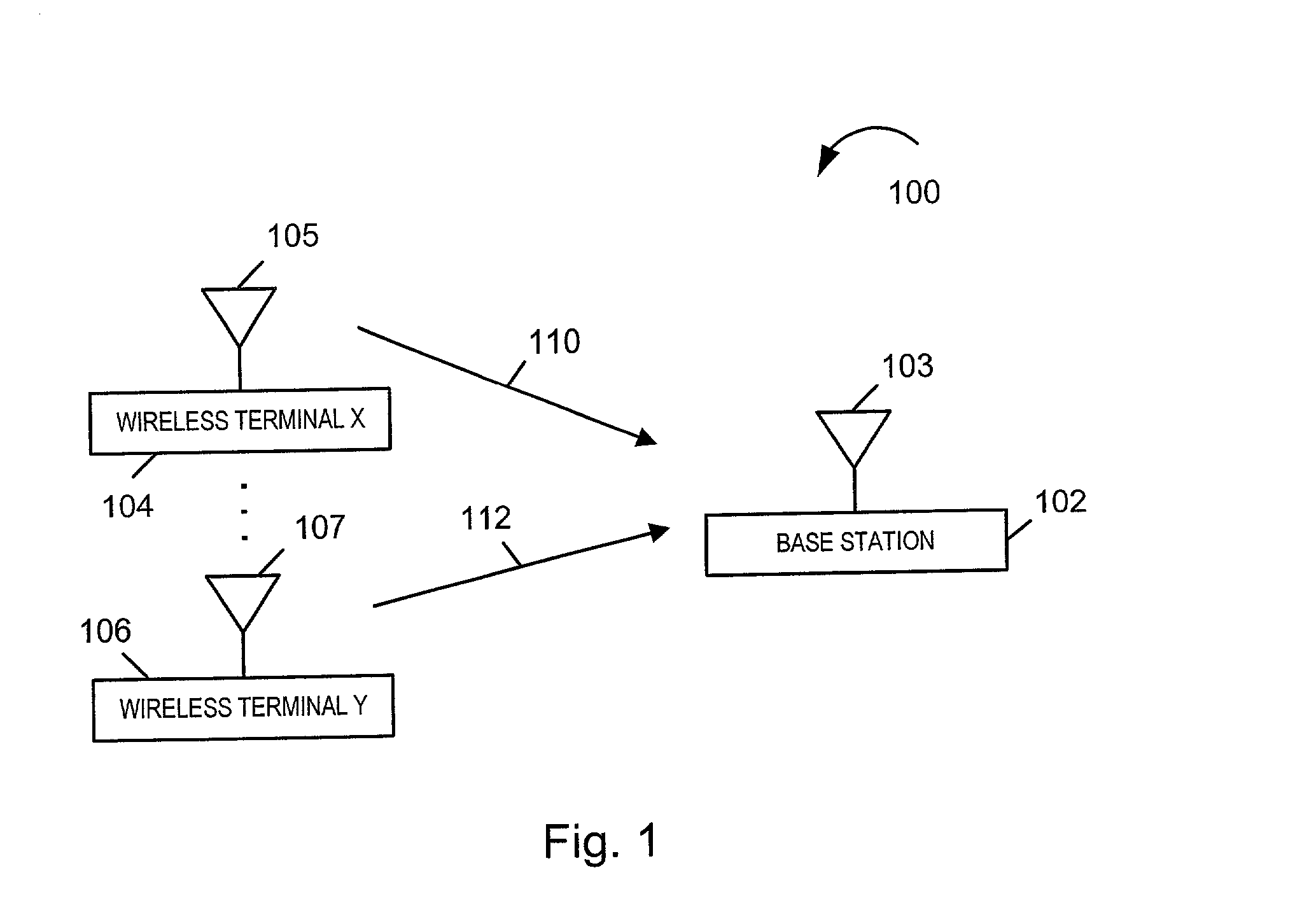
[0031] FIG. 1 shows an exemplary OFDM multiple access system 100 in which several first communication devices, that is, wireless terminals 104, 106, e.g., mobile stations, transmit OFDM signals 110, 112 to a second communication device, that is a single base station 102, simultaneously. Signals 110, 112 each include one or more symbols, e.g., OFDM symbols. The wireless terminals 104, 106 include antennas 105, 107 for the transmission of signals 110, 112. Base station 102 includes antenna 103 for receiving the transmitted signals 110, 112.

[0032] In the exemplary system 100, OFDM symbols comprise two parts, a cyclic prefix and an FFT body. FIG. 9 illustrates an example of such an OFDM symbol 900 which includes a total of N samples. The cyclic prefix 902 includes K samples whil...


PUM


Abstract

Symbol timing synchronization in OFDM communication systems where multiple wireless terminals communicate with a single base station is described. Base station transmitter and receiver symbol timing is fixed. Each wireless terminal operates to independently adjust its transmitter timing. Transmitter timing synchronization at the wireless terminal is slaved to the terminal's receiver timing synchronization. Each wireless terminal first corrects its receiver symbol timing based on a signal received from the base station. The wireless terminal then adjusts its transmitter symbol timing as a function of its receiver symbol timing. When the receiver symbol timing is to be advanced or delayed by some amount, the transmitter symbol timing is also advanced or delayed, respectively, by the same, or substantially the same, amount. Symbol timing adjustment can be made by adding or deleting digital samples from the first or last symbol in a dwell.

Description

RELATED APPLICATIONS[0001] This application claims the benefit of U.S. Provisional Application Ser. No. 60 / 274,987 filed Mar. 9, 2001.FIELD OF THE INVENTION[0002] The present invention relates to communications systems and, more particularly, to methods and apparatus for performing symbol timing, e.g., in frequency division multiplexed systems.BACKGROUND OF INVENTION[0003] In communication systems, e.g., radio or other wireless systems, the transmitter and the receiver frequently do not have access to a common clock source. Instead, there are likely two clocks running separately, one at the transmitter and another at the receiver. In wireless systems, base stations typically have very accurate clocks. However, due to cost considerations, wireless terminals, e.g., mobile telephones and / or other mobile communications devices, often use inexpensive clocks. In many cases, such inexpensive clocks are less accurate than the clocks used in the base stations with which the mobile stations i...

Claims


Application Information

Patent Timeline
IPC IPC(8): H04B7/26H04L5/02H04J11/00H04L7/00H04L7/033H04L27/26H04W56/00
CPCH04L5/023H04L7/0334H04L27/2662H04W56/0005H04W56/0045H04L27/2646H04B7/208
Inventor LAROIA, RAJIVLI, JUNYIPARIZHSKY, VLADIMIR
Owner QUALCOMM INC
Learn More