Method and apparatus for forward link power control

a forward link and power control technology, applied in power management, wireless communication, transmission, etc., can solve the problems of excessive interference with the received signals, remote stations can receive erroneous data transmissions, and limited reverse link capacity, so as to improve the response time of the forward link power control loop, and minimize interference to other base stations

Inactive Publication Date: 2002-09-12
QUALCOMM INC
View PDF0 Cites 26 Cited by
  • Summary
  • Abstract
  • Description
  • Claims
  • Application Information

AI Technical Summary

Benefits of technology

0020] The present invention is a novel and improved method and apparatus for high rate forward link power control. The present invention improves the response time of the forward link power control loop and allows for dynamic adjustment of the transmission power on the forward link by measuring the quality of the reverse link power control bits which are transmitted on the forward traffic channel a...

Problems solved by technology

Therefore, the reverse link capacity is limited by the total interference due to transmissions from other remote stations.
A high transmission power from the base station can cause excessive interference with the signals received at other remote stations.
Alternatively, if the transmission power of the base station is too low, the remote station can receive erroneous data transmissions.
Terrestrial channel fading and other known factors can affect the quality of the forward link signal as received by the remote station.
One of the disadvantages of this method is ...

Method used


Image

  • Method and apparatus for forward link power control
  • Method and apparatus for forward link power control
  • Method and apparatus for forward link power control

Examples


first embodiment

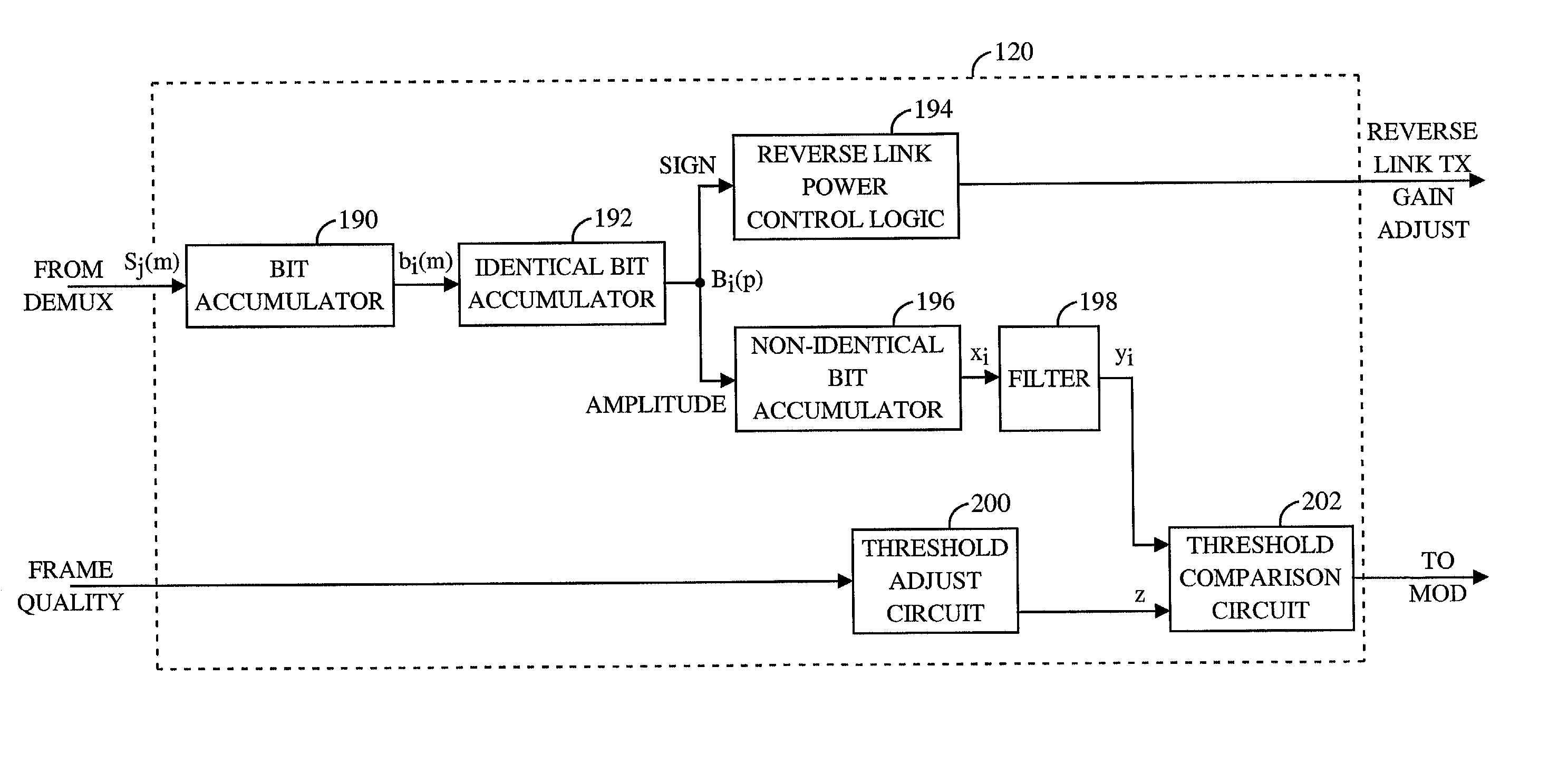
[0072] In the first embodiment, threshold adjust circuit 200 updates the value of z according to the equation: 3 z k = { z k - 1 + e k - 1 = 1 z k - 1 - e k - 1 = 0 , ( 3 )

[0073] where z.sub.k is the target energy level at the k.sup.th frame, e.sub.k-1 is the frame error at the (k-1).sup.th frame, .gamma. is the size of an upward step to be applied to the target energy level, and .delta. is a size of a downward to be applied to the target energy level. In the exemplary embodiment, e.sub.k-1 is set equal to 1 if there was a frame error for the (k-1).sup.th data frame and 0 otherwise. The values for .gamma. and .delta. are selected to provide a desired level for the FER. Typically, .gamma. is large and .delta. is small. This selection creates a sawtooth-like pattern for z.sub.k. When a frame error occurs, z.sub.k increases substantially to minimize the probability of another frame error. When there is no frame error, z.sub.k slowly decays to minimize the transmission power. In the exe...

second embodiment

[0074] In the second embodiment, the stepsizes .gamma. and .delta. can be made functions of the current target energy level z.sub.k-1 so that the correction to z.sub.k is dependent on the current target energy level. Thus, equation (3) can be modified as: 4 z k = { z k - 1 + ( z k - 1 ) e k - 1 = 1 z k - 1 - ( z k - 1 ) e k - 1 = 0 . ( 4 )

[0075] In the exemplary embodiment, remote station 6 completes demodulation of the data frame and updates the target energy level z.sub.k during the middle of the succeeding frame. If the (k-1).sup.th data frame is received in error, the probability of a frame error for the k.sup.th data frame is greater. This is because any adjustment to the target energy level will not have an immediate impact on the FER performance until the system has had sufficient time to make a transition to the new operating point. Therefore, the second of two consecutive frame errors should not be interpreted as indicative of the performance of the target energy level valu...

third embodiment

[0087] In a third embodiment, shown in the bottom diagram of FIG. 7, the forward link power control bit is transmitted as a short pulse of approximately 0.41 msec in duration at a predetermined amount of time ("delay2" in FIG. 7) after reception of the reverse link power control bit on the forward traffic channel. The duration of the forward link power control bit is chosen to be small enough so that it will be finished by the time the following forward link power control bit is to be sent, even in the worst case when the latest possible time slot is used in the current power control group and the earliest possible time slot is to be used in the following power control group. In the exemplary embodiment, the amount of delay is set to 0.050 msec (delay2=0.050 msec). As illustrated in FIG. 7, this embodiment entails higher transmission power for the duration of the pulse in order to transmit the same amount of energy over a shorter pulse duration. One drawback of this method is that t...


PUM

PropertyMeasurementUnit
Poweraaaaaaaaaa
Transmissionaaaaaaaaaa
Phaseaaaaaaaaaa

Abstract

A forward link power control mechanism measures the reverse link power control bits which are transmitted on the forward traffic channel. At the remote station, the reverse link power control bits from multiples base stations or multiple signal paths are measured, combined, and filtered to yield an improved measurement of the forward link signal quality. The reverse link power control bits which are deemed unreliable are omitted from use in the power control loop. The remote station generates a set of forward link power control bit in accordance with the measurements and transmits these bits to all base stations in communication with the remote station. Each base station adjusts its gain of the forward traffic channel in accordance to its measurement of the forward link power control bit.

Description

CROSS REFERENCE[0001] This application is a continuation application of U.S. application Ser. No. 08 / 842,993, filed Apr. 25, 1997, entitled "Method and Apparatus for Forward Link Power Control" and currently assigned to the assignee of the present application.BACKGROUND OF THE INVENTION[0002] I. Field of the Invention[0003] The present invention relates to data communication. More particularly, the present invention relates to a novel and improved method and apparatus for the forward link power control in a communication system.[0004] II. Description of the Related Art[0005] The use of code division multiple access (CDMA) modulation techniques is one of several techniques for facilitating communications in which a large number of system users are present. Other multiple access communication system techniques, such as time division multiple access (TDMA) and frequency division multiple access (FDMA) are known in the art. However, the spread spectrum modulation techniques of CDMA have...

Claims


Application Information

Patent Timeline
IPC IPC(8): C08L23/04C08L23/06C08L23/08C08L23/10C08L23/12C08L23/16H04B1/04H04B7/005H04B7/26H04W52/08H04W52/24H04W52/40
CPCC08L23/04C08L23/06C08L23/08C08L23/0815C08L23/0853C08L23/12C08L23/16C08L2205/02H04W52/08H04W52/24H04W52/40C08L2666/04H04B7/005
Inventor TIEDEMANN, EDWARD G. JR.SAINTS, KEITH W.
Owner QUALCOMM INC
Why Eureka
Try Eureka