Microwave gas decomposition reactor

a gas decomposition reactor and microwave technology, applied in the field of gas decomposition, can solve the problems of harmful emissions of hydrofluorocarbons (hfcs) by industrial processes, such as semiconductor processes, when released into the atmosphere, and achieve the effect of facilitating gas decomposition

Inactive Publication Date: 2002-09-12
MINAEE BRUCE +2
View PDF0 Cites 28 Cited by
  • Summary
  • Abstract
  • Description
  • Claims
  • Application Information

AI Technical Summary

Benefits of technology

0009] The present invention is a microwave reactor for decomposing waste green house gases resulting from the manufacture of semiconductors and from other industrial. The microwave reactor includes a plasma chamber having a gas inflow port spaced apart from a gas outflow port for transporting gases through the plasma chamber. A gas plasma is generated in the plasma chamber to facilitate the gas decomposition. The structure of the microwave reactor includes an insulating cover protruding into the plasma chamber and forming an internal cavity that is isolated from gases in the plasma chamber. A microwave antenna extends into the internal cavity of the plasma chamber to couple the microwave energy in

Problems solved by technology

Certain gases such as Perfluorinated Compounds (PFCs) including nitrogen trifloride, NF.sub.3, and sulfurhexafloride, SF.sub.6, and hyd

Method used


Image

  • Microwave gas decomposition reactor
  • Microwave gas decomposition reactor
  • Microwave gas decomposition reactor

Examples


Embodiment Construction

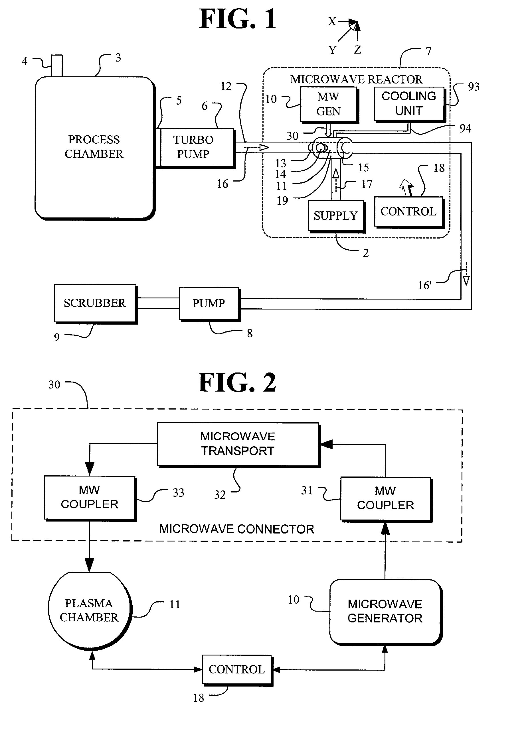
[0023] In FIG. 1, the process chamber 3 is used for industrial processes that exhaust green house gases such as PFCs and HFCs. Such gases are frequently found in the semiconductor industry. The industrial process chamber 3 includes an input port 4 for receiving input reactants used in the industrial process and an output port 5 for exhausting gases 16. A turbo pump 6 is connected to pump the gases from the process chamber 3 and deliver the exhaust gases 16 to the gas line 12. The gas line 12 connects to a microwave reactor 7 which operates to process the exhaust gases 16. The microwave reactor 7 has a plasma chamber 11 with an inflow port 13, an outflow port 15 and one or more other ports 14. The diameter of inflow port 13 conveniently matches the diameter of the outflow port of the turbo pump 6 or is otherwise connected so that exhaust gases 16 enter the inflow port 13 with a minimum of back pressure resulting from the piping connections. The plasma chamber 11 is connected with exh...


PUM


Abstract

A microwave reactor for decomposing waste green house gases resulting from the manufacture of semiconductors and from other industrial processes. The microwave reactor includes a plasma chamber having a gas inflow port spaced apart from a gas outflow port for transporting gases through the plasma chamber. A gas plasma is generated in the plasma chamber to facilitate the gas decomposition. The structure of the microwave reactor includes an insulating cover protruding into the plasma chamber and forming an internal cavity that is isolated from gases in the plasma chamber. A microwave antenna extends into the internal cavity of the plasma chamber to couple the microwave energy into plasma chamber for causing a plasma to form in the gases.

Description

CROSS REFERENCE[0001] PROCESS GAS DECOMPOSITION REACTOR, invented by Bruce Minaee, filed May 17, 2000 and having SC / Ser. No. 09 / 572,111.BACKGROUND OF THE INVENTION[0002] The present invention relates to the field of gas decomposition and, more particularly, to a microwave reactor for decomposing waste gases resulting from the manufacture of semiconductors and from other industrial processes.[0003] Certain gases such as Perfluorinated Compounds (PFCs) including nitrogen trifloride, NF.sub.3, and sulfurhexafloride, SF.sub.6, and hydrofluorocarbons (HFCS) emitted by industrial processes, such as semiconductor processes, are harmful when released into the atmosphere. PFCs and HFCs are categorized as greenhouse gases because of their strong infrared absorption and long atmospheric lifetimes. PFCs and HFCs act similar to CO.sub.2 in causing thegreenhouse effect. Because of their potential long term impact on the global climate, PFC's, HFC's, NF.sub.3 and SF.sub.6 have been included in the...

Claims


Application Information

Patent Timeline
IPC IPC(8): B01D53/00
CPCB01D53/007
Inventor MINAEE, BRUCEFARNAAM, KAMBIZAYVAZYAN, RAFIK GRANT
Owner MINAEE BRUCE
Why Eureka
Try Eureka