Display apparatus

a technology for display panels and components, applied in the field of display apparatuses, can solve the problems of inability to easily replace defect parts, increase in cost, undesirable reduction of heat transfer from display panels to chassis, etc., and achieve the effect of simplifying the disassembly process and facilitating the peeling operation

Inactive Publication Date: 2002-09-12
PIONEER DISPLAY PROD CORP
View PDF0 Cites 11 Cited by
  • Summary
  • Abstract
  • Description
  • Claims
  • Application Information

AI Technical Summary

Benefits of technology

[0011] The present invention has been made to solve such problems, and therefore an object of the present invention is to provide a display apparatus capable of facilitating a peeling operation while maintaining an adhesion area required between a display panel and a chassis, and of simplifying a disassembling process for recycling and a parts replacing process.
[0017] The present invention having the above features yields the following operation and effects. In order to achieve a construction allowing smooth peeling in addition to ensuring an adequate adhesion area and adhesive strength, the construction can use a plurality of double-faced adhesive tapes to ensure a required adhesion area and adhesive strength equal to that of the sum total of the double-faced adhesive tapes and allows the tapes to be individually peeled in the peeling operation. With this point in mind, the present invention has a parallel arrangement of a plurality of double-faced adhesive tapes having a predetermined width in the width direction. Each of the arranged double-faced adhesive tapes can be pulled individually in the longitudinal direction to produce strain in the width direction, and the produced strain produces a peel force allowing each double-faced adhesive tape to be individually peeled off from its originally bonded position.
[0018] More specifically, a base material of the double-faced adhesive tape consists of materials having a high elasticity. When the double-faced adhesive tape is pulled in the longitudinal direction, the base material contracts in the width direction by the amount of strain resulting from "the strain in the longitudinal direction.times.Poisson's ratio". The strain in the width direction produces a peel force (shear force) which is utilized for peeling the double-faced adhesive tape adhering between the display panel and the chassis. In other words, in the situation where a plurality of double-faced adhesive tapes are interposed between the back surface of the display panel and the chassis for adhesion, when an end of one of the double-faced adhesive tapes is pulled in the longitudinal direction, the tape is extended in the longitudinal direction and concurrently undergoes contraction in the width direction (or in the thickness direction) in proportion to the extension, and the resulting strain causes a peel force on the adhesion portion. The peel force (shear force) at this point takes a value formed by multiplying the strain in the width direction by Young's modulus (modulus of lateral elasticity) of the double-faced adhesive tape. If in relation to the peel force, the sum total (shear adhesive strength) of an adhesive strength between one adhering face of the double-faced adhesive tape and the back surface of the display panel and an adhesive strength between the other adhering face of the double-faced adhesive tape and the mating face of the chassis, is set to be lower, then the double-faced adhesive tape can be peeled only by being pulled as described above. In practical terms, when the shear adhesive strength of the double-faced adhesive tape stands at equal to or smaller than about 60 N / cm.sup.2, this allows the tape to be peeled.
[0019] When the base material of the double-faced adhesive tape has a tensile strength higher than a tensile force required for peeling, it is possible to pull out the tape without breaking it. In practical terms, when the double-faced adhesive tape has a breaking elongation rate of more than or equal to 300 percent (i.e. the tape has such a strength as not to be broken even when the base material elongates three times or more its original length), the tape can be pulled out from between the display panel and the chassis.
[0020] Further, each of the double-faced adhesive tapes is disposed such that its end protrudes outwardly beyond ends of both the display panel and the chassis or beyond an end of one of those. This design facilitates pulling the end of the double-faced adhesive tape in the situation where a plurality of the double-faced adhesive tapes are interposed between the back surface of the display panel and the chassis for attaching the display panel to the chassis.

Problems solved by technology

However, in order to peel off the double-faced adhesive tape, the aforementioned conventional construction needs a special peeling method using solvents, heating, water pressure or the like, leading to the problem of an increase in cost.
Further, when a display panel has a defect while still on a production line or needs to be repaired after the shipment of product, the aforementioned conventional construction has been proved difficult to separate the display panel from the chassis, leading to a problem that defect parts can not be easily replaced.
In this case, however, a gap is likely to occur between the display panel and chassis, which causes another problem that an amount of heat transferred from the display panel to the chassis will be undesirably reduced.
Further, if the adhesion area is reduced, a temperature difference may occur between an adhesion part and a non-adhesion part, thus causing a thermal stress strains on the display panel, leading to the problem of the display characteristics being affected by the thermal stress strain.

Method used


Image

  • Display apparatus
  • Display apparatus
  • Display apparatus

Examples


Embodiment Construction

[0026] A preferred embodiment according to the present invention will be described hereinafter with reference to the accompanying drawings (the same components as those of the prior art are designated by the same reference numerals and the repeated part of the description is omitted).

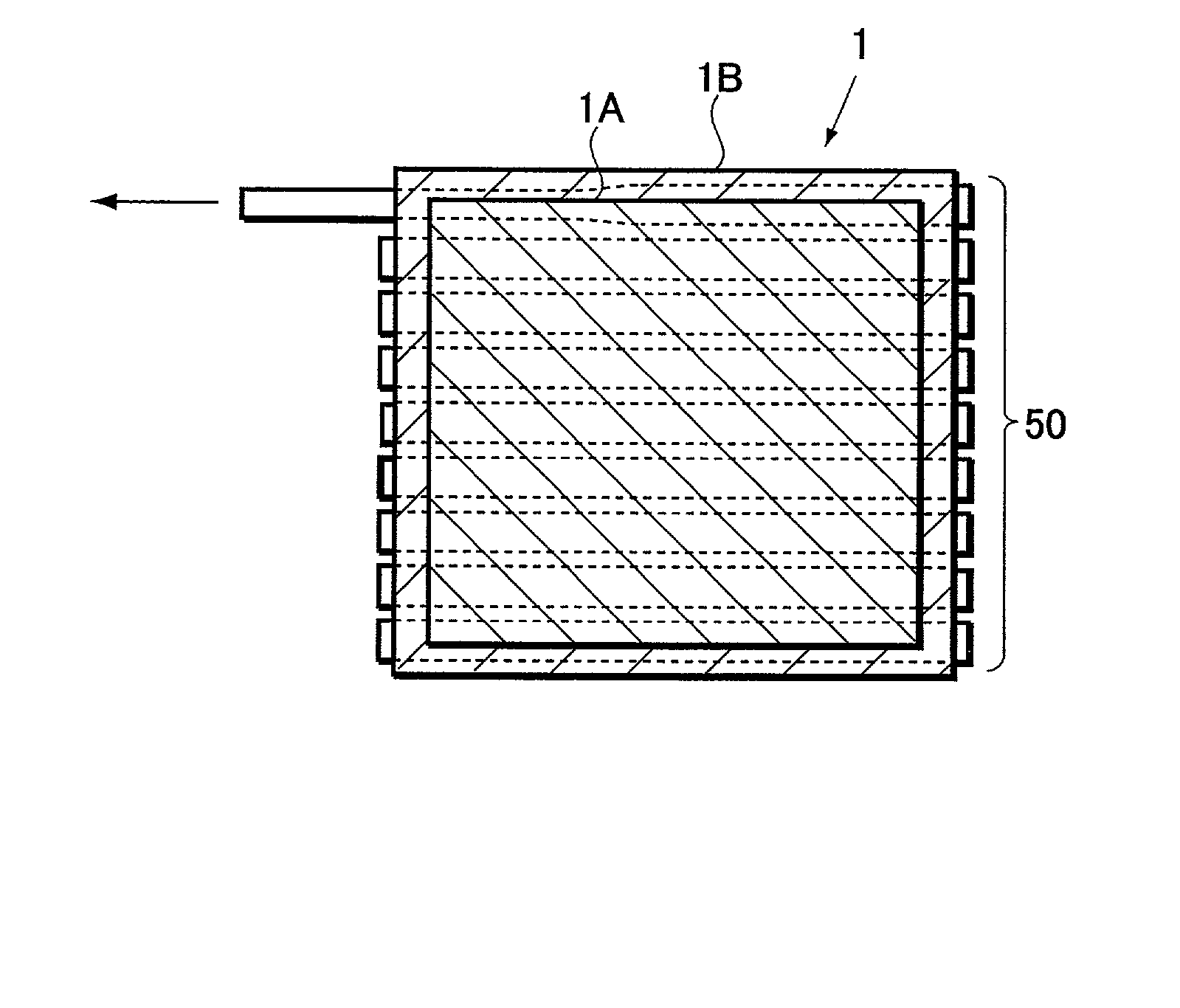
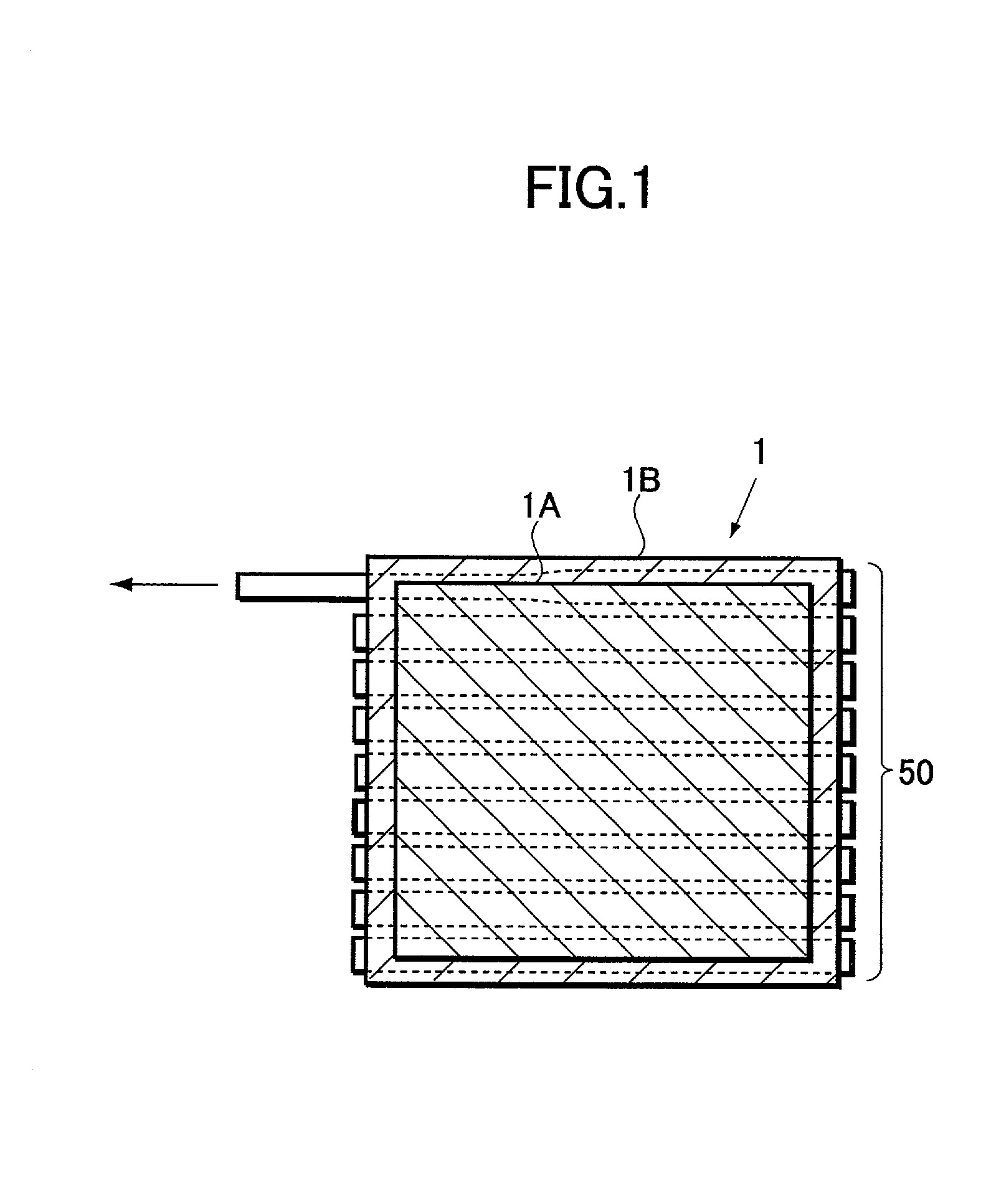
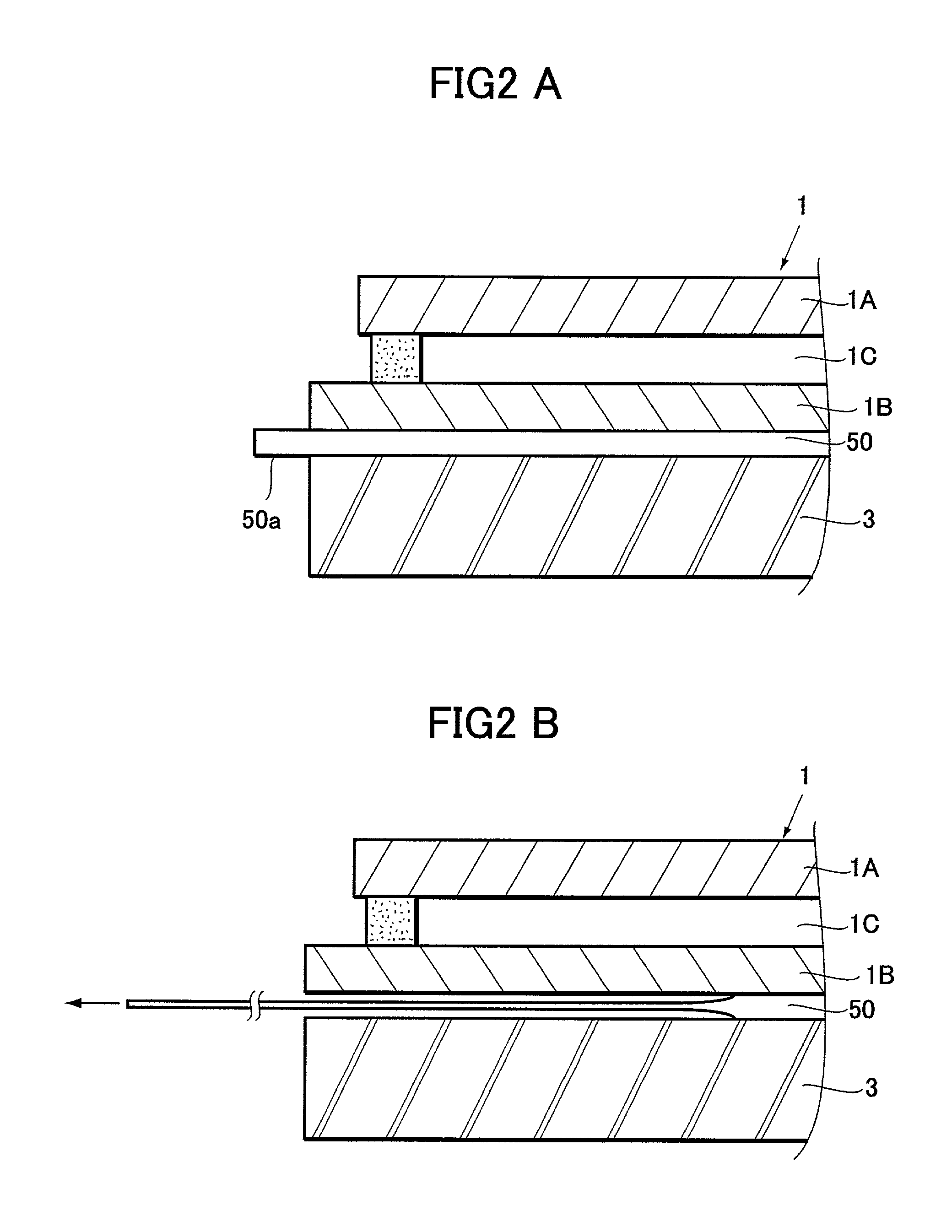
[0027] FIG. 1 and FIGS. 2A and 2B are explanatory diagrams for illustrating the construction of a display apparatus according to a preferred embodiment of the present invention, in which FIG. 1 is a plan view and FIGS. 2A and 2B are side views. The illustrated display apparatus has a PDP (Plasma Display Panel) 1 which is configured such that a front glass substrate 1A and a back glass substrate 1B are bonded together with a discharge space 1C between. To the back surface of the PDP 1 a chassis 3 is attached with a plurality of double-faced adhesive tapes 50 interposed therebetween. The chassis 3 is made of a metal such as aluminum, and so configured as to cover at least the entire back surface of the ba...


PUM

PropertyMeasurementUnit
breaking elongation rateaaaaaaaaaa
adhesive strengthaaaaaaaaaa
shear adhesive strengthaaaaaaaaaa

Abstract

An effortless peeling operation is provided with maintaining the adhesion area required between a display panel and a chassis, which allows a disassembling operation for recycling and a parts replacement operation to be simplified. A plasma display apparatus includes a plurality of double-faced adhesive tapes 50 interposed between and adhering to the back surface of a display panel 1 and a chassis 3 for attaching the chassis 3 to the display panel 1. The double-faced adhesive tape 50 used has an adhesive strength smaller than a peel force produced by strain in a width direction caused by tension in a longitudinal direction, and the tape 50 is pulled in the longitudinal direction for peeling.

Description

BACKGROUND OF THE INVENTION[0001] 1. Field of the Invention[0002] This invention relates to a display apparatus employing a plasma display panel, a field emission display (FED) panel or the like. More particularly, it relates to a display apparatus in which a fixation between a display panel and a chassis has been improved so that the two elements can be easily separated from each other when the apparatus is discarded for recycling.[0003] The present application claims priority from Japanese Application No. 2001-67279, the disclosure of which is incorporated herein by reference for all purposes.[0004] 2. Description of the Related Art[0005] A known display apparatus includes a plasma display panel (hereinafter referred to as "PDP") comprising row electrode pairs and column electrodes which are arranged on the respective inner surfaces of a pair of substrates, disposed opposite to each other with a discharge space formed between, so as to form a discharge cell at each intersection of...

Claims


Application Information

Patent Timeline
Patent Type & Authority Applications(United States)
IPC IPC(8): B29C65/76B32B7/10G09F9/00H01J5/50H01J5/58H01J17/28
CPCB29C65/76B32B7/10H01J5/50H01J5/58H01J9/52Y02W30/828Y10T428/14Y02W30/82
Inventor KANEKO, KOICHIOISHI, TOSHIHARUNOZAWA, MASARUYOKOI, SADAOKAKIHARA, MASAHIKOMIYAMURA, YUKIHARUOHNUMA, KAZUHIRO
Owner PIONEER DISPLAY PROD CORP
Why Eureka
Try Eureka