Torsional vibration damper

a torsional vibration and damper technology, applied in the direction of yielding couplings, mechanical devices, couplings, etc., can solve the problems of undesirable friction engagement between the intermediate convolutions of the coil spring and the adjacent portions of the two components, internal surfaces, and inconvenient us

Inactive Publication Date: 2002-09-12
LUK LAMELLEN & KUPPLUNGSBAU BETEILIGUNGS KG
View PDF9 Cites 40 Cited by
  • Summary
  • Abstract
  • Description
  • Claims
  • Application Information

AI Technical Summary

Benefits of technology

0006] An object of the present invention is to reduce, preferably to zero or close to zero, friction between the compression coil spring or springs and the surfaces bounding the chamber defined by those components of a torsion vibration damper which can turn relative to each other by overcoming the resistance of the coil spring or springs.

Problems solved by technology

A drawback of the just described conventional torsional vibration damper is that, when the two components are driven to rotate jointly at a high speed, the intermediate convolutions of the coil spring move or tend to move radially outwardly under the action of centrifugal force and come into pronounced frictional engagement with the internal surfaces which surround the arcuate chamber being defined by the two components.
Such frictional engagement between the intermediate convolutions of the coil spring and the adjacent portions of the two components is undesirable on several grounds.
For example, the internal surfaces of the two components and the surfaces of the radially outermost portions of the intermediate convolutions of the coil spring undergo pronounced wear and generate heat which must be dissipated, often at a high cost involving time and / or material, e.g., due to the need for the use of expensive materials for the components and / or due to the need for the application of highly wear-resistant coatings or the like.

Method used


Image

  • Torsional vibration damper
  • Torsional vibration damper
  • Torsional vibration damper

Examples


Embodiment Construction

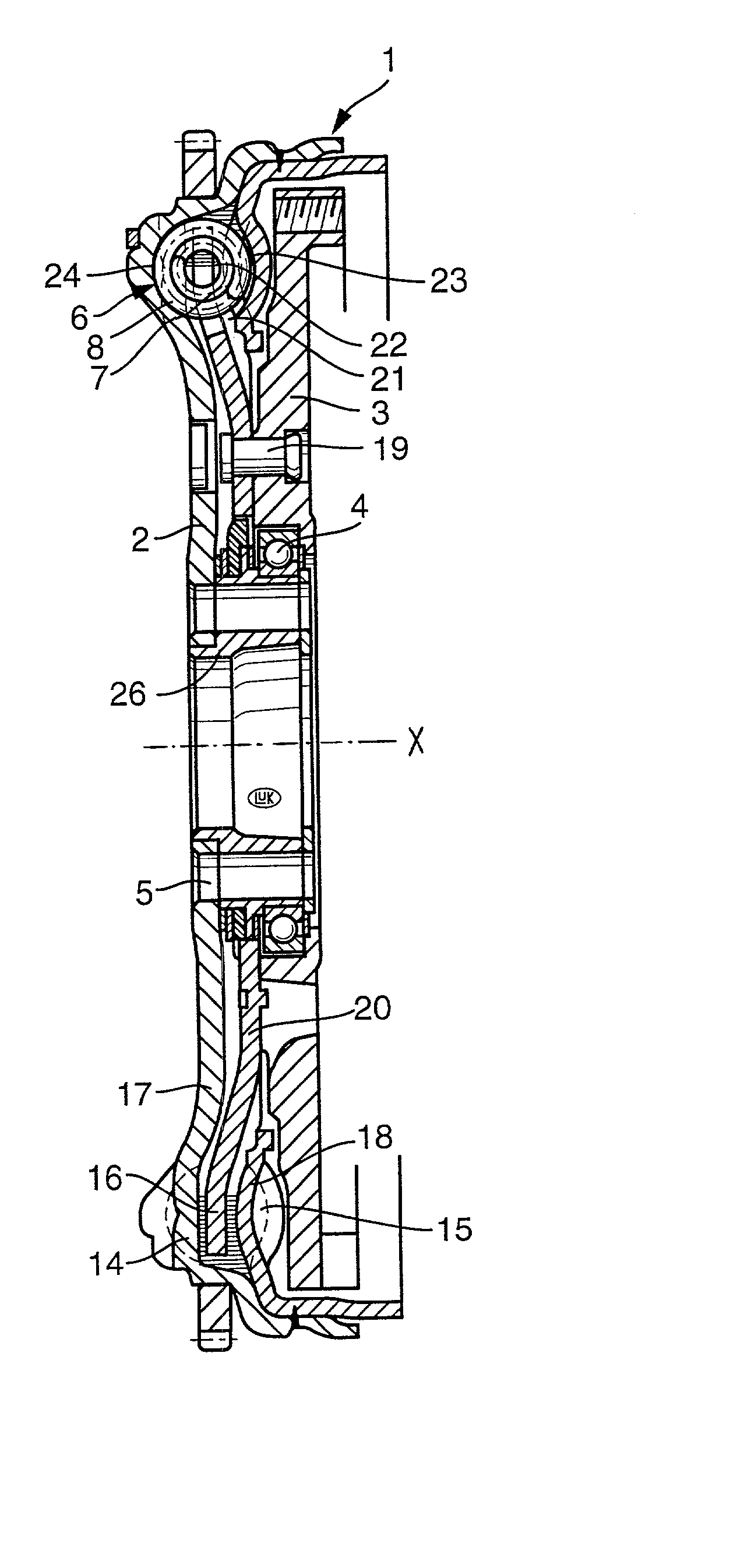
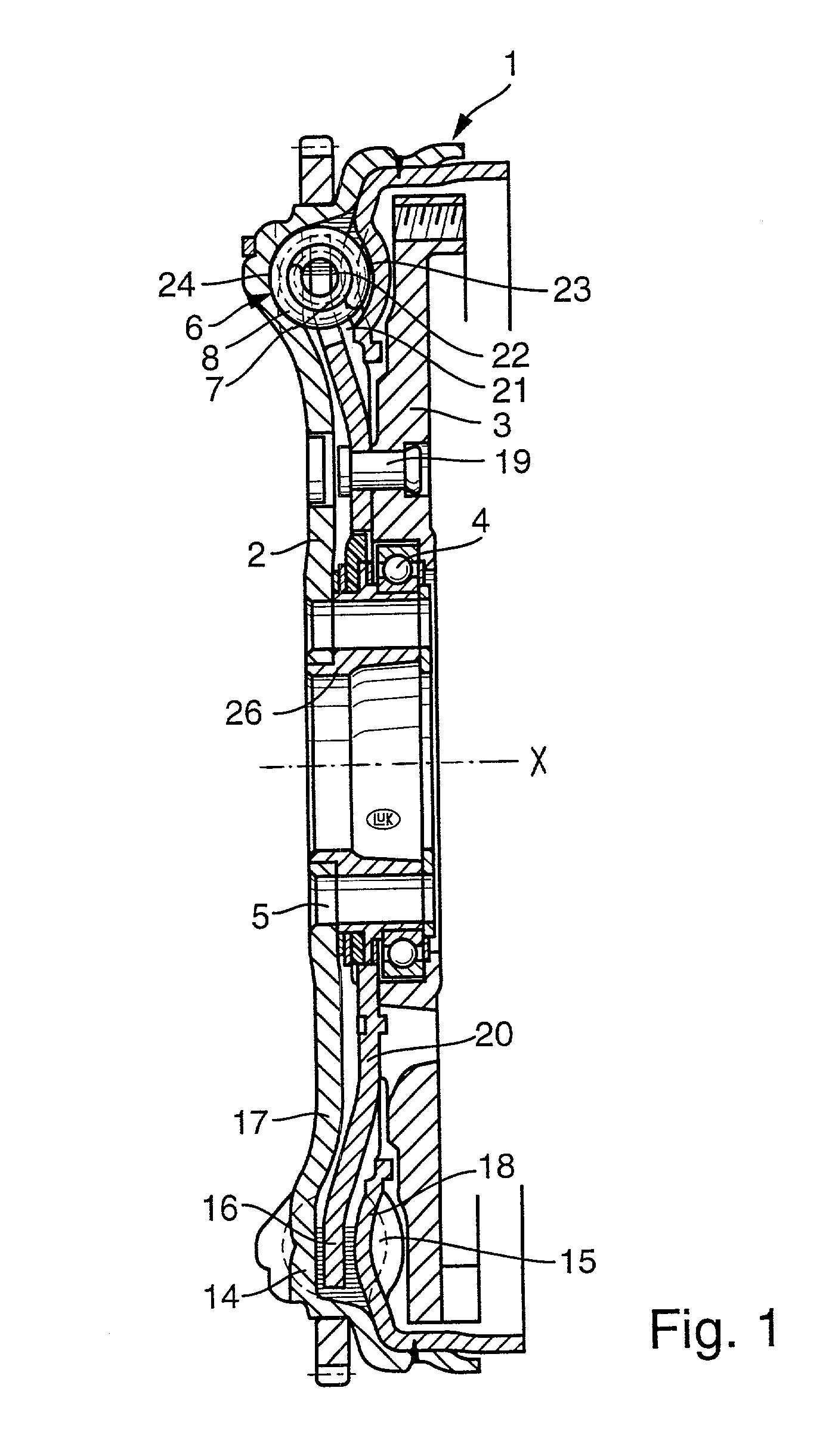
[0057] Referring to FIGS. 1 and 2, there is shown a torsional vibration damper 1 which is a composite flywheel and is assumed to be mounted in the power train of a motor vehicle including a prime mover, such as an internal combustion engine having a rotary output element (e.g., a camshaft or a crankshaft) serving to drive a first rotary component 2 (primary flywheel) of the damper 1. The output element of the prime mover is affixed to the component 2 by a set of bolts or analogous fasteners, not shown, extending through holes 5 provided in a central portion 26 of the component 2. The illustrated central portion 26 is a hub which surrounds the input shaft (not shown) of the change-speed transmission in the power train.

[0058] The damper 1 further comprises a second rotary component (secondary flywheel) which, in the embodiment of FIGS. 1 and 2, is assembled of two parts, namely a shell 3 and a washer-like part 20 riveted (at 19) to the shell 3. The shell 3 can constitute the counterpr...


PUM


Abstract

A torsional vibration damper, particularly for use in the power train of a motor vehicle, employs one or more preferably arcuate coil springs having constant inner radii and one or more sets of neighboring smaller-diameter convolutions next to one or more sets of neighboring larger-diameter convolutions. The coil spring or springs is or are compressible by the retainers of two components which can turn, about a common axis, with and relative to each other and at least one of which defines a chamber for the coil spring(s). The retainers of the components can act upon the adjacent end convolutions of the coil spring or of two or more series-arranged coil springs between them by way of plastic slide elements and/or elastic bumpers. One or more plastic slides can partially surround selected convolutions to maintain it or them out of contact with the surface surrounding the coil spring(s) even when such spring or springs is or are being acted upon by centrifugal force in response to high-speed rotation of the components.

Description

CROSS-REFERENCE TO RELATED CASES[0001] This patent application claims the priority of the commonly owned copending German patent application Serial No. 101 11 055.3 filed Mar. 8, 2001. The disclosure of this copending German patent application, as well as that of each U.S. and foreign patent and patent application identified in the specification of the present application, is incorporated herein by reference.BACKGROUND OF THE INVENTION[0002] This invention relates to improvements in torsional vibration dampers of the type wherein two coaxial rotary components are turnable relative to each other against the opposition of one or more one-piece or composite coil springs. Torsional vibration dampers of such character can be utilized with advantage in the power trains of motor vehicles, e.g., they can constitute composite flywheel assemblies between the output shafts of prime movers (such as the crankshafts or camshafts of internal combustion engines) and the housings or pressure plates ...

Claims


Application Information

Patent Timeline
Patent Type & Authority Applications(United States)
IPC IPC(8): F16F15/121F16F1/06F16F1/08F16F1/12F16F15/134F16F15/137F16F15/139F16F15/30
CPCF16F1/08F16F15/13438F16F15/13453F16F15/13461F16F15/137F16F15/121
Inventor JACKEL, JOHANNMENDE, HARTMUTZHOU, BIN
Owner LUK LAMELLEN & KUPPLUNGSBAU BETEILIGUNGS KG
Why Eureka
Try Eureka