

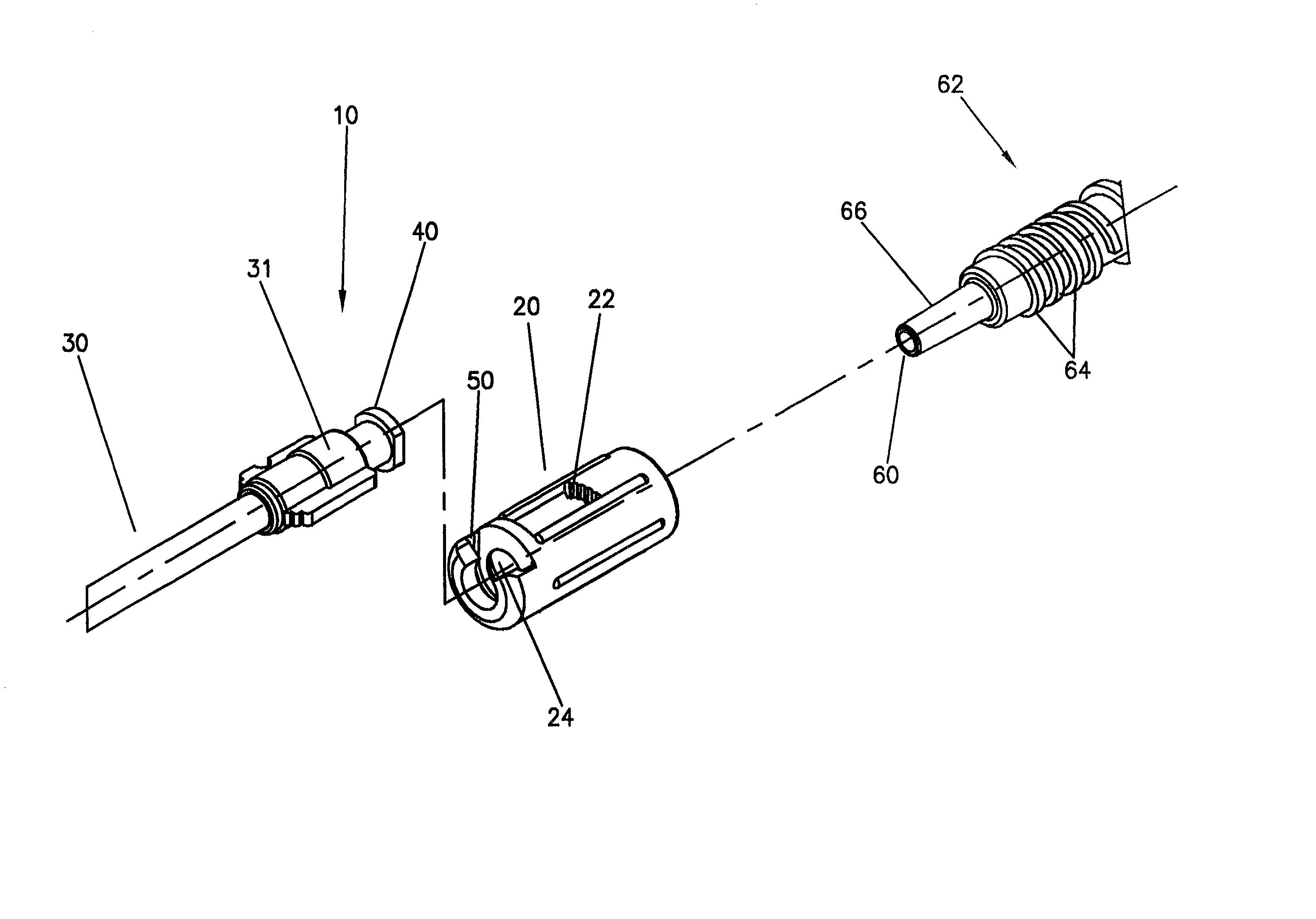
Connector and tubing assembly for use with a syringe
a technology of connecting tubing and syringe, which is applied in the direction of catheters, rigid containers, transportation and packaging, etc., can solve the problems of wasting time and effort for medical practitioners in preparing and conducting injection procedures, and the possibility of patient contamination, so as to reduce the number of non-sterile surfaces and handling steps, reduce the time required, and minimize the possibility of contamination of the fluid path
- Summary
- Abstract
- Description
- Claims
- Application Information
AI Technical Summary
Benefits of technology
Problems solved by technology
Method used
Image

Examples
Embodiment Construction
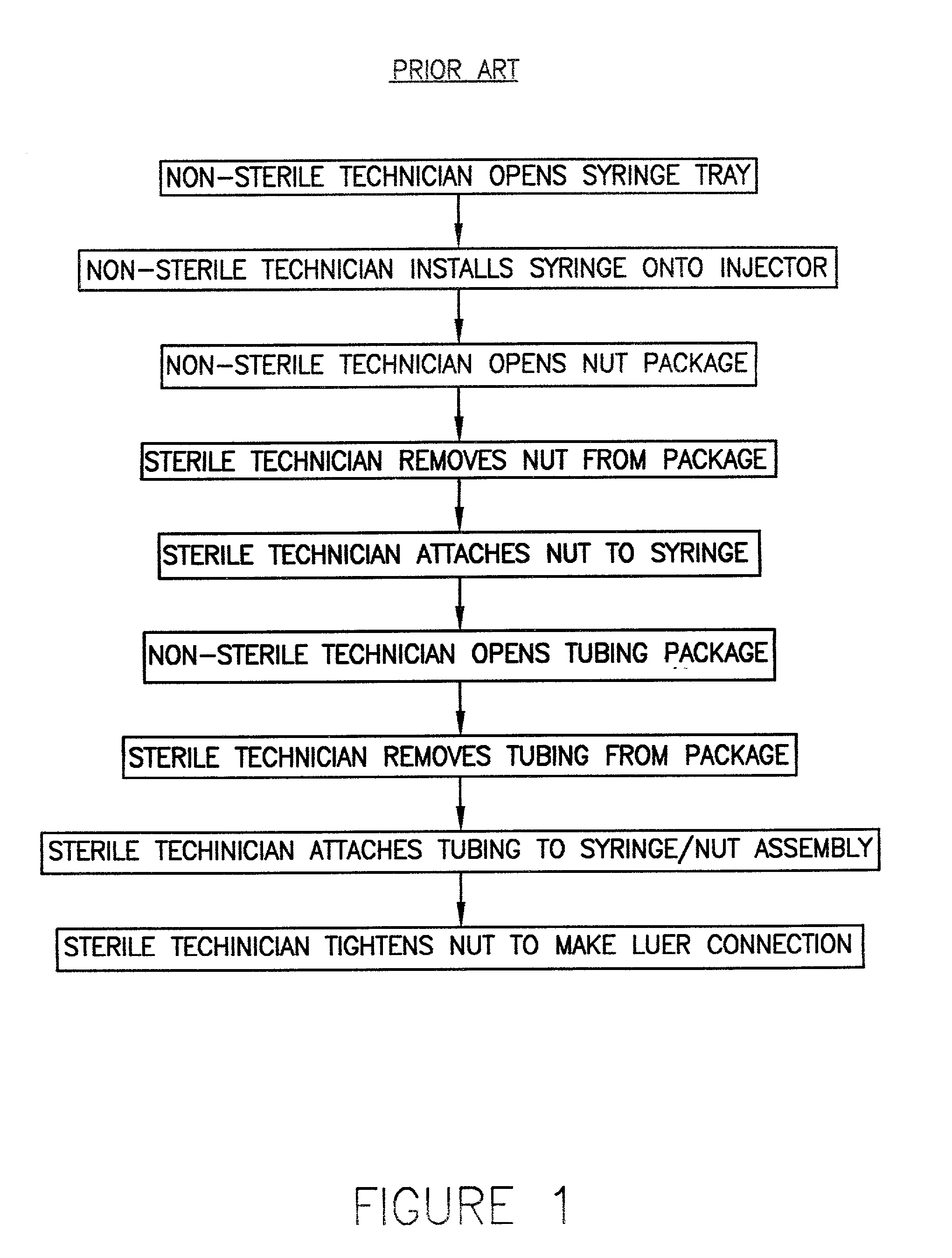
[0026] As recited above and as illustrated in FIG. 1, the conventional method for loading a prefilled syringe onto an injector includes many time-consuming steps and requires the handling of a number of components having non-sterile surfaces, thereby increasing the risk of patient contamination.
[0027] Specifically, as shown in FIG. 1, the following method is currently performed for installing or loading a syringe onto an injector: (1) a non-sterile technician in the injection suite opens the sealed tray containing a syringe and a syringe nut package; (2) the non-sterile technician installs or loads the syringe onto the injector; (3) the non-sterile technician opens the syringe nut package to provide access to the sterile syringe nut and removes the tip cap from the nozzle of the syringe; (4) a second, sterile technician in the injection suite removes the sterile syringe nut from the opened syringe nut package; (5) the sterile technician attaches the syringe nut to the syringe; (6) t...
PUM
| Property | Measurement | Unit |
|---|---|---|
| melt temperature | aaaaa | aaaaa |
| melting point | aaaaa | aaaaa |
| time | aaaaa | aaaaa |
Abstract
Description
Claims
Application Information