
Container for intravenous administration

a container and intravenous technology, applied in the direction of hose connections, packaging foodstuffs, packaged goods types, etc., can solve the problems of extra routine, contamination, faulty handling, etc., and requires a certain skill and accuracy

Inactive Publication Date: 2002-09-12
FREZENIUS KABI AB
View PDF0 Cites 28 Cited by
  • Summary
  • Abstract
  • Description
  • Claims
  • Application Information

AI Technical Summary

Benefits of technology

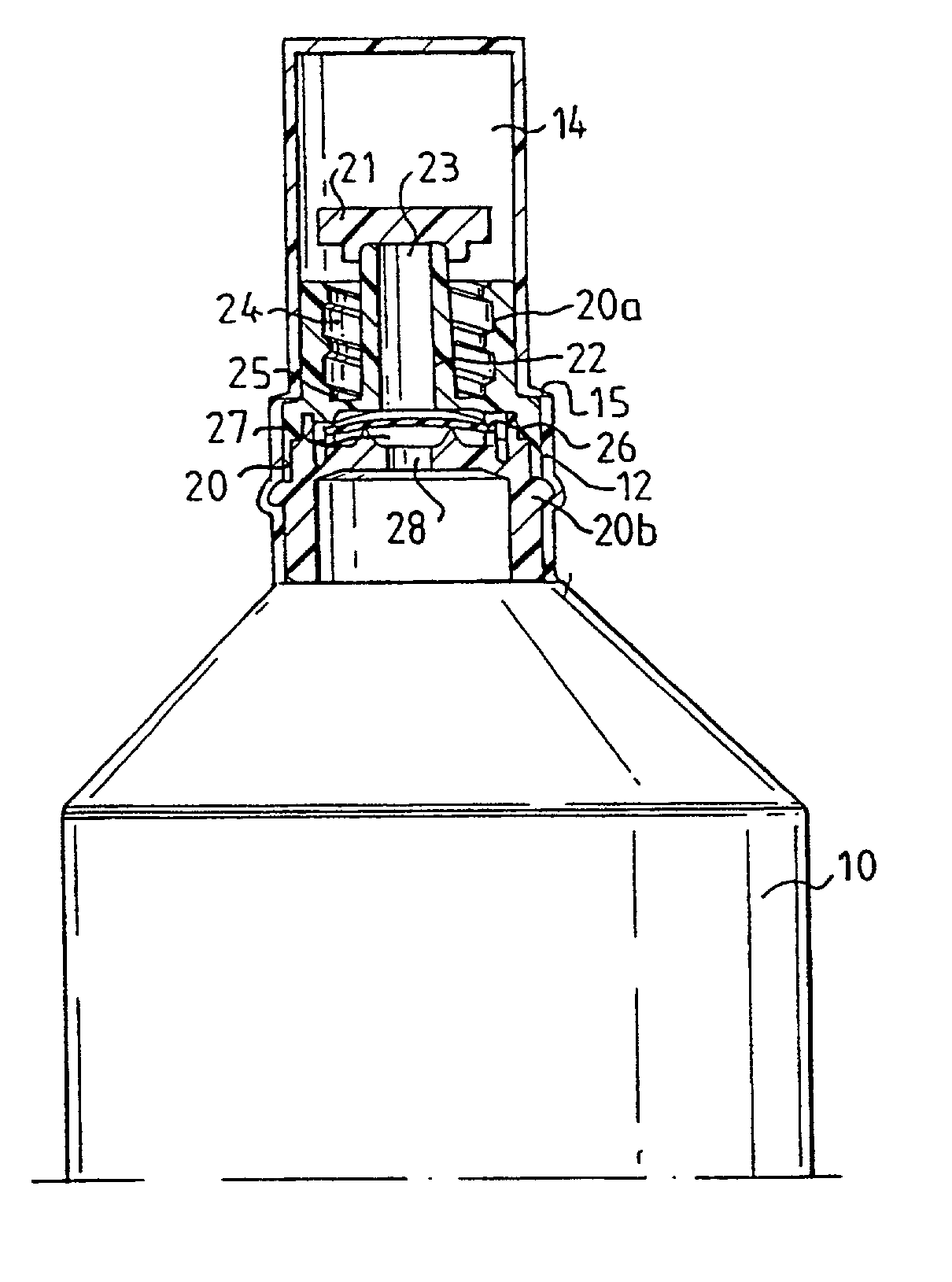
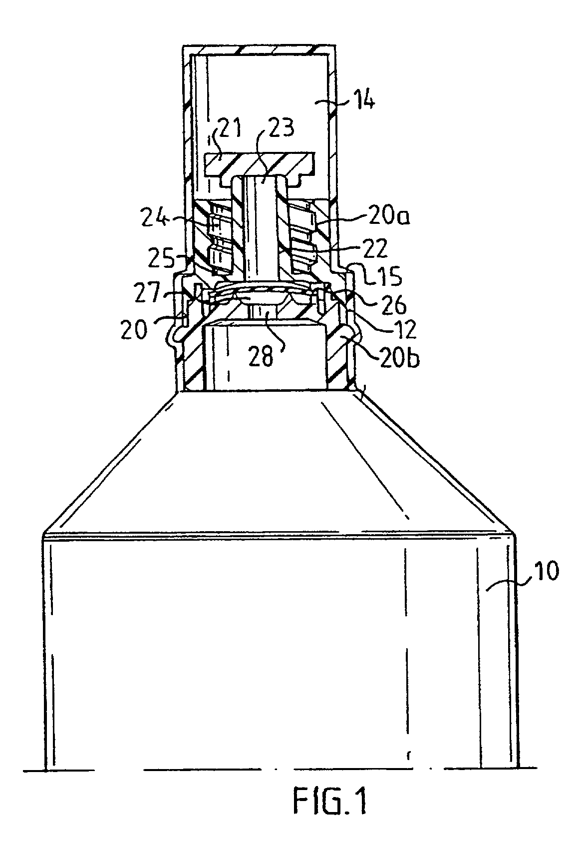
[0007] The present invention relates to a device for storing and administering a medical fluid, comprising a sealed flexible container which is generally bottle formed or of a similar shape. In its front end, the container is provided with an opening part, in which an insert is sealingly positioned. In order to protect the insert during handling and storing prior to the use of the device, the container is formed during its manufacturing so it directly extends into sealing cap over said insert. The cap is removable by being provided with weak line or a similarly rupturable zone so the user by a simple twisting motion may remove the entire cap or a substantial part thereof to expose the insert when the fluid in the container shall be used and fluid communication shall be established between the container and an attachable injection means, preferably with a conventionally shaped cannula comprising a front needle part connected to generally conical hollow rear part. This is accomplished by that the rear part of the cannula is attached to a generally tubular part of the insert with a generally conical shape in cross-section fitting with the hollow part of the cannula. Preferably, the tubular part of the insert and the hollow part of the cannula are cooperating luer fittings, so said tubular part corresponds to male luer fitting and said hollow part corresponds to a female luer fitting. Furthermore, to ensure that the injection means is safely attached, the insert is provided with a engagement means which comprises a radially extended annular recess in the insert which extends axially into the insert a sufficient distance to secure the attachment of a conventional cannula having a rear end shaped as a female luer fitting. To improve on the engagement, the outer periphery of the annular recess preferably is provided with screw threaded grooves, so as to form a luer lock attachment between the cannula and the insert of the device.

Problems solved by technology

A drawback with these containers is that it requires a certain skill and accuracy to correctly pierce the insert to establish fluid communication between the bottle and syringe so as to collect a desired amount of stored fluid for adminstration to a patient or for transfer to another container.
The transferring step using an attachable syringe results in an extra routine and thereby a risk for contamination and faulty handling.
At first, the inserting procedure of the connector is inconvenient and results in additional handling for the hospital personal and will always include a risk for inadvertent contamination of the fluid.
Secondly, the device, if used for vein flushing, may deliver air bubbles with the fluid when the fluid is administered by squeezing the flexible bottle.
The introduction of air bubbles into the blood system can not be tolerated due to the risk of embolism
However, as injection devices these containers in many aspects are inferior when compared to ordinary syringes operating by actuating a piston rod connected to a piston during the administration of the fluid.
One drawback with conventional blow-fill-seal formed containers of this type is that the joints from the molding process when connecting the container pieces remain and cause impairments of the fitting of luer connection between the container top and a cannula.
It is of further importance that they do not admit any safe routines when it comes to removing air bubbles from the injection fluids, as being performed by a routine de-aeration step with conventional syringes in order to avoid injection of air.
U.S. Pat. No. 5,538,306 reveals a construction of such a bottle formed squeezable containers attachable to a cannula which aims to overcome the problems, but is complicated in construction and requires a prescribed handling including several steps.

Method used


Image

  • Container for intravenous administration
  • Container for intravenous administration

Examples


Embodiment Construction

[0007] The present invention relates to a device for storing and administering a medical fluid, comprising a sealed flexible container which is generally bottle formed or of a similar shape. In its front end, the container is provided with an opening part, in which an insert is sealingly positioned. In order to protect the insert during handling and storing prior to the use of the device, the container is formed during its manufacturing so it directly extends into sealing cap over said insert. The cap is removable by being provided with weak line or a similarly rupturable zone so the user by a simple twisting motion may remove the entire cap or a substantial part thereof to expose the insert when the fluid in the container shall be used and fluid communication shall be established between the container and an attachable injection means, preferably with a conventionally shaped cannula comprising a front needle part connected to generally conical hollow rear part. This is accomplished...


PUM


Abstract

A device for storing and administering a medical fluid comprising a sealed flexible formed container with an opening part in its front end in which an insert is positioned. Over the insert, the container extends into a removable sealing cap. After removal of the sealing cap an injection means is attached to the insert and fluid administration through the insert is admitted in one direction by squeezing the container.

Description

FIELD OF INVENTION[0001] The present invention relates to a device for storing and administering a medical fluid, comprising a sealed flexible generally bottle formed container provided with an insert in its opening to which an injection means can be attached.BACKGROUND OF THE INVENTION[0002] It is a well established technique in pharmaceutical industry to manufacture prefilled bottle formed containers for sterile fluids from blow molding a polymer material, filling and sealing the so formed container in a continuous operation. Such a blow-fill-seal method is disclosed for example in U.S. Pat. No. 4,342,184. In the European patent specification EP 0 670 709, it is disclosed a container made from such a method comprising essentially only a polyolefin based material so a highly environmental friendly container is obtained with a high compatibility to the stored fluids which also satisfies the requirement that the finally sealed container shall be sterilized with high pressure steam (i...

Claims


Application Information

Patent Timeline
Patent Type & Authority Applications(United States)
IPC IPC(8): A61J1/00A61J1/10A61J1/14A61J1/20
CPCA61J1/18A61J1/2096B65D47/24Y10S604/905A61J1/201A61J1/1425A61J1/1487A61J1/1481A61J1/1468
Inventor ANDERSSON, GUNNARPETTERSON, BERT
Owner FREZENIUS KABI AB
Learn More