Power management under limited power conditions

a power management and limited power technology, applied in the field of power systems, can solve the problems of not allowing the current mission, affecting the operation of the entire bus, etc., and achieve the effect of rapid and efficient manner

Inactive Publication Date: 2002-09-12
SIKORSKY AIRCRAFT CORP
View PDF0 Cites 56 Cited by
  • Summary
  • Abstract
  • Description
  • Claims
  • Application Information

AI Technical Summary

Problems solved by technology

Entire busses may be subject to cut-off, typically by an electromechanical relay, in cases of severe generating capacity loss.
Disadvantageously, a block reduction approach requires that the mix of critical and less-critical loads be determined at the time the vehicle is designed and hard-wired into the power system.
This categorization may be based on a predefined set of assumptions and generator conditions which may unnecessarily de-energize particular equipment upon generator degradation and thus may not allow for current mission circumstances.

Method used


Image

  • Power management under limited power conditions
  • Power management under limited power conditions
  • Power management under limited power conditions

Examples


Embodiment Construction

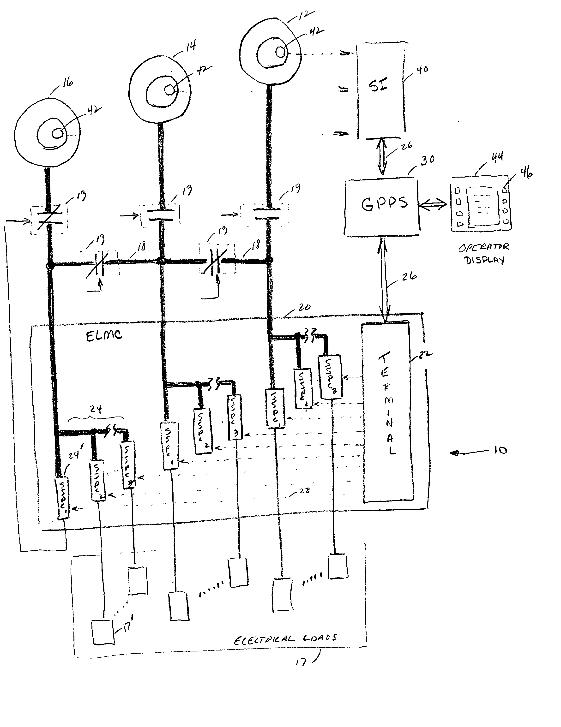
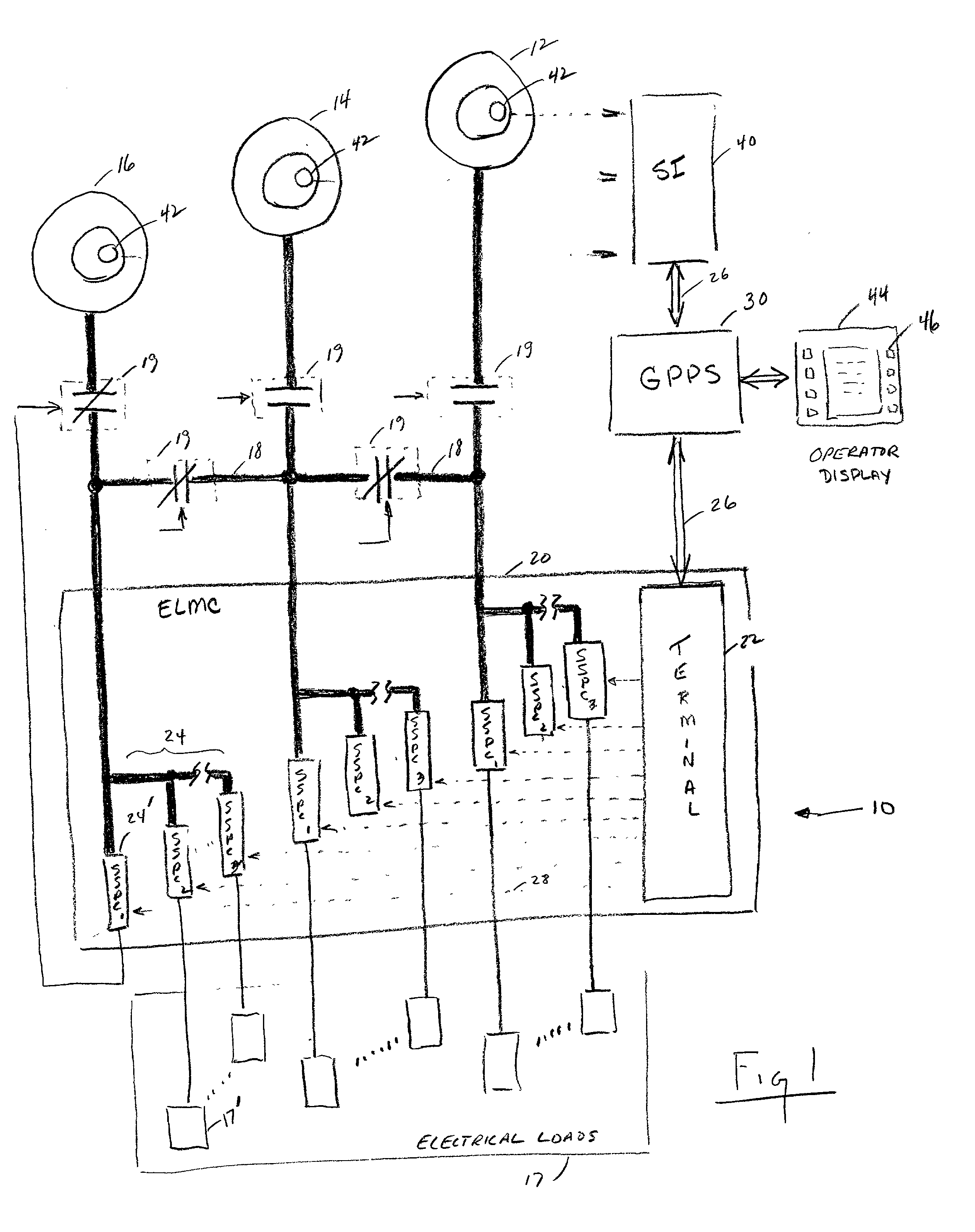
[0020] FIG. 1 schematically illustrates a vehicle power system 10 which includes a multiple of electrical generators. The system 10 includes a first and a second electrical generator 12,14 and a subsystem power unit (SPU) electrical generator 16 which provide power for vehicle electrical loads 17 through an electrical load management center (ELMC) 20. Each electrical load is representative of a particular vehicle system such as weapon systems, communication systems, counter measure systems, navigation systems, etc., which are powered by the vehicle power system 10.

[0021] The ELMC 20 contains a remote terminal section 22 and at least one set of solid state power controllers (SSPC; illustrated schematically at 24). Each SSPC 24' is associated with a particular electrical load 17' such that the power supplied to each electrical load 17' may be individually controlled by the associated SSPC 24'. Although each set of SSPCs 24' in the disclosed embodiment includes (3) SSPCs 24'; it should...


PUM


Abstract

A vehicle power system includes a multiple of electrical generators which provide power for vehicle electrical systems or loads through an electrical load management center which communicates with a general purpose processor set such that the power supplied to each electrical load may be individually controlled. A display communicates with the GPPS to present an electrical system status screen to the vehicle crew such that the crew is constantly made aware of the prevailing electrical power conditions in a rapid and efficient manner. During a drastically reduced generator situation, the GPPS automatically disconnects loads via a predefined load shed priority list. Once electrical loads are disconnected via the predefined load shed priority list the crew can reactivate and deactivate selected systems for the current mission circumstances through a load recovery screen accessible through the display.

Description

BACKGROUND OF THE INVENTION[0001] This invention was made with government support under Contract No.: DAAJD991-C-A004 awarded by the Department of the Army. The government therefore has certain rights in this invention.[0002] The present invention relates to a power system, and more particularly to the control of electric loads during a generator failure in a multi-generator system.[0003] A power system for a vehicle typically includes two or more generators for redundancy. When one of the generators fails it is necessary to switch vital equipment that was supplied by the failed generator to a working generator. In order to prevent the remaining generator(s) from being overloaded when the additional loads are connected, it is necessary to disconnect, or shed, some of the lower priority loads before other equipment loads are transferred.[0004] One known power system includes a #1 generator associated with a #1 primary bus and a #1 monitor bus. A #2 generator is provided to power a #2...

Claims


Application Information

Patent Timeline
Patent Type & Authority Applications(United States)
IPC IPC(8): B60L15/20B60L15/36H02J3/00H02J3/14
CPCB60L15/2045B60L15/36H02J3/006H02J3/14Y02T90/16Y10T307/391Y10T307/615Y10T307/724Y10T307/625Y02T10/7283H02J3/0073H02J2310/44Y02T10/72Y04S20/222Y02B70/3225
Inventor SODOSKI, ANTHONY F.HAMILTON, BRUCE S.BRADFORD, MICHAEL P.
Owner SIKORSKY AIRCRAFT CORP
Why Eureka
Try Eureka