Web infeed for a rotary printing press

a rotary printing press and web infeed technology, applied in the direction of thin material handling, filament handling, article delivery, etc., can solve the problems of inconvenience, web was broken, and unnecessarily large web dimension

Inactive Publication Date: 2002-09-19
TOKYO KIKAI SEISAKUCHI LTD
View PDF0 Cites 51 Cited by
  • Summary
  • Abstract
  • Description
  • Claims
  • Application Information

AI Technical Summary

Benefits of technology

0011] The present invention has it as an object to make the web infeed of

Problems solved by technology

An objection to this Japanese patent is an unnecessarily great dimension of the web infeed axially of the carrier beam, or transversely of the web being into the press.
This inconvenience arises in part from the fact that both cylinders on each pair of carrier arms are equi

Method used


Image

  • Web infeed for a rotary printing press
  • Web infeed for a rotary printing press
  • Web infeed for a rotary printing press

Examples


Embodiment Construction

General

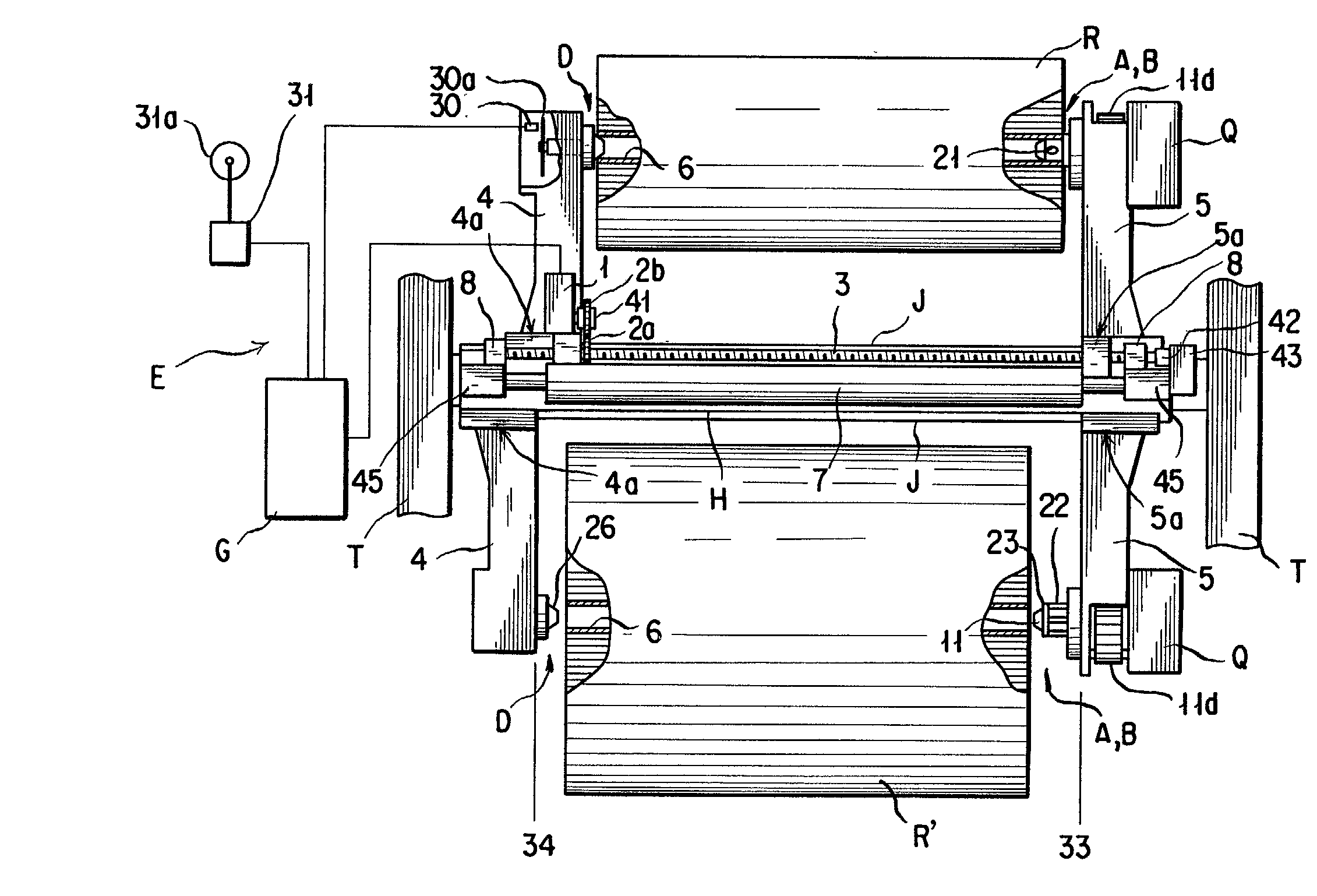
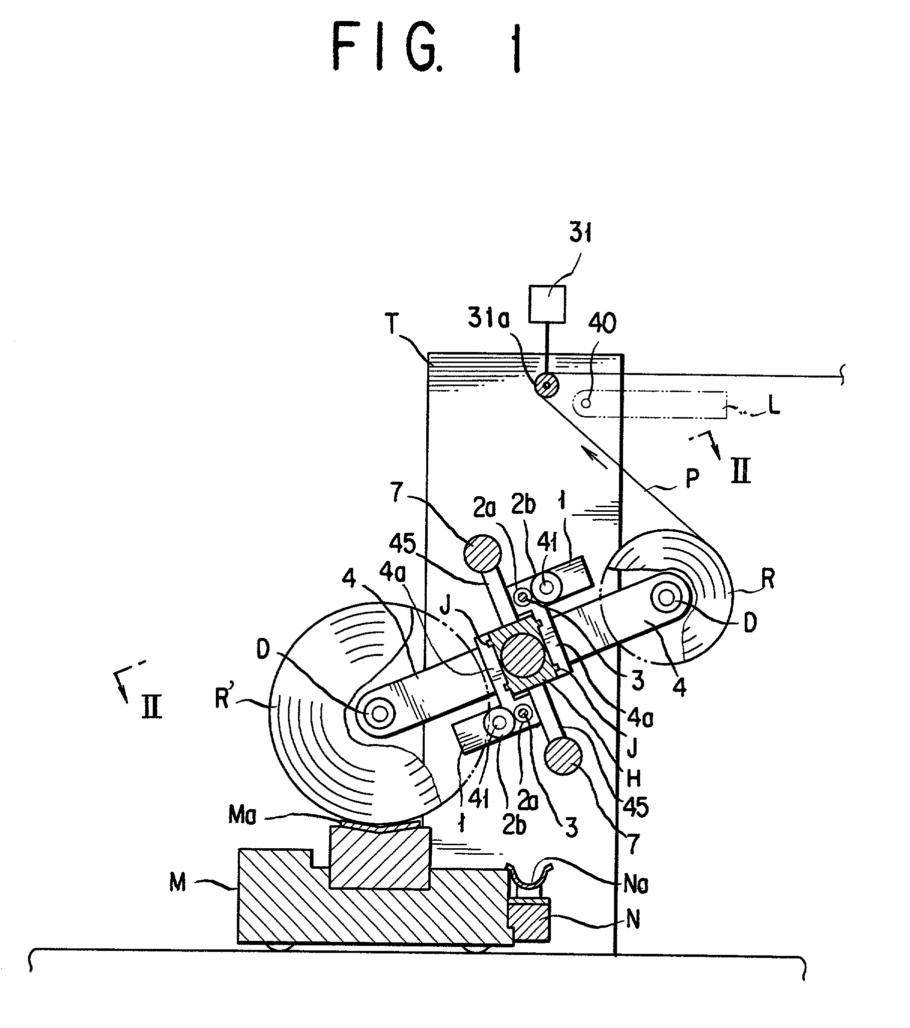
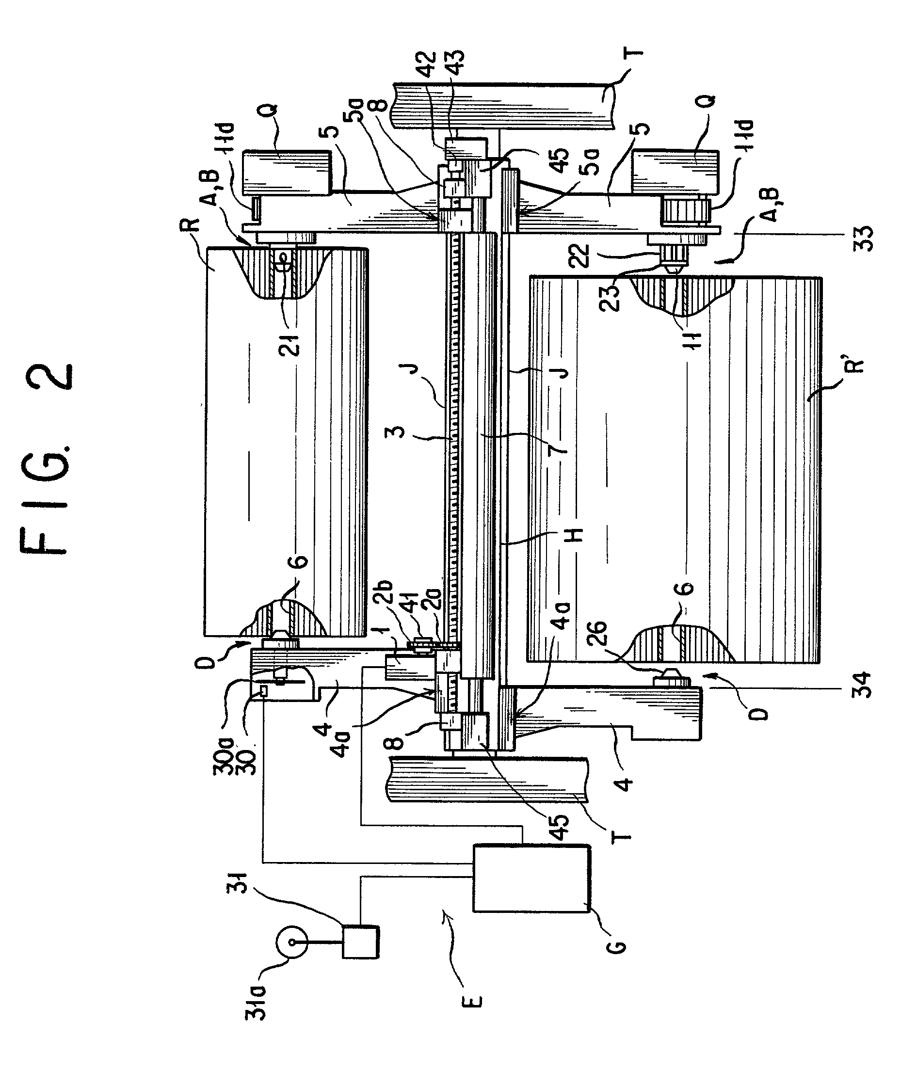
[0031] The representative web infeed for a rotary printing press, shown in its entirety in FIGS. 1 and 2, has a rotary carrier beam H of generally square cross section for carrying the various working parts and components of the web infeed to be set forth hereinbelow. Extending horizontally, the carrier beam H has its opposite ends rotatably journaled in a pair of confronting, upstanding framing walls T of the press. It is understood that a drive mechanism, not shown, of any known or suitable design is coupled to the carrier beam H for revolving the same. On each of a pair of opposite side surfaces of the carrier beam H there are formed a pair of guide rails J extending longitudinally of the beam. Two pairs of carrier arms 4 and 5 are mounted on the respective pairs of guide rails J via shoes 4a and 5a for sliding motion longitudinally of the carrier beam H.

[0032] A closer inspection of FIGS. 1 and 2 will reveal that one roll R of paper web is supported between one pair of ca...


PUM

PropertyMeasurementUnit
Forceaaaaaaaaaa
Diameteraaaaaaaaaa
Displacementaaaaaaaaaa

Abstract

A rotary beam has mounted thereon a pair of carrier arms for rotatably supporting a roll of web from which the web is fed into the press, and another such arm pair for supporting another such web roll to which the web is to be spliced upon consumption of the first web roll. One of each pair of carrier arms has rotatably mounted thereto a hollow spindle to be partly inserted in the tubular core of the web roll. The hollow spindle has detents arranged at circumferential spacings thereon for fluid pressure actuation into frictional engagement with the inside surface of the web roll core. The other of each carrier arm pair has a second spindle rotatably mounted thereto which is to be held endwise against the web roll core via a spring-loaded end cap. How hard the web roll core is urged against the first spindle by the second spindle, resisting the unwinding of the web therefrom, depends upon whether the second spindle is held fast against the end cap or spaced therefrom by the spring. The second spindle is sprung away from the end cap upon decrease of the web roll diameter to a predefined limit, in order to mitigate tension on the web being paid out.

Description

BACKGROUND OF THE INVENTION[0001] 1. Field of the Invention[0002] This invention relates to web-fed rotary printing presses in general and, in particular, to a mechanism incorporated with such a press for infeeding a web of paper into the machine from successive web rolls as the web is spliced from one such roll to the next.[0003] 2. Description of the Prior Art[0004] A familiar type of web infeed for a rotary printing press has two pairs of web roll carrier arms extending in opposite directions from a rotary arm carrier beam. Each pair of carrier arms rotatably carry a roll of paper web therebetween by engaging the opposite ends of the tubular core of the web roll. Held in a prescribed angular position about the axis of the carrier beam, the web roll on one pair of carrier arms first pays out its web to feed the press. When this web roll is nearly used up, the carrier beam is turned 90 degrees for splicing the web to the next web roll on the second pair of carrier arms. The carrier...

Claims


Application Information

Patent Timeline
IPC IPC(8): B65H16/06B65H16/10B65H19/12B65H19/18
CPCB65H16/06B65H16/103B65H19/126B65H19/1836B65H2301/41346B65H2301/41856B65H2403/52B65H2408/241
Inventor NAKAMURA, DAISUKEOGAWA, YUKIO
Owner TOKYO KIKAI SEISAKUCHI LTD
Why Eureka
Try Eureka