Electrophoretic medium and process for the production thereof

Inactive Publication Date: 2002-09-19
E INK CORPORATION
View PDF99 Cites 338 Cited by
  • Summary
  • Abstract
  • Description
  • Claims
  • Application Information

AI Technical Summary

Benefits of technology

0048] From the foregoing, it will be seen that the present invention can be used to form the electrophoretic medium in the form of layers less than 50 .mu.m in thickness. Indeed, the present invention can be used to prepare electrophoretic media in layers as thin as 20 .mu.m, and possibly even thinner. Such thin layers have the advantage that they reduce the operating voltage and/or switching time of an electrophoretic display. Obviously, for any layer of a specific electrophoretic medium, the operating voltage required is proportional to the thickness of the medium. Also, at any given field strength the switching time of the medium is directly proportional to the distance which the electrophoretic particles must move to effect switching, and this distance is substantially equal to the thickness of a droplet perpendicular to the substrate. Accordingl

Problems solved by technology

Nevertheless, problems with the long-term image quality of these displays have prevented their widespread usage.
For example, particles that make up electrophoretic displays tend to cluster and settle, re

Method used


Image

  • Electrophoretic medium and process for the production thereof
  • Electrophoretic medium and process for the production thereof
  • Electrophoretic medium and process for the production thereof

Examples


example 2

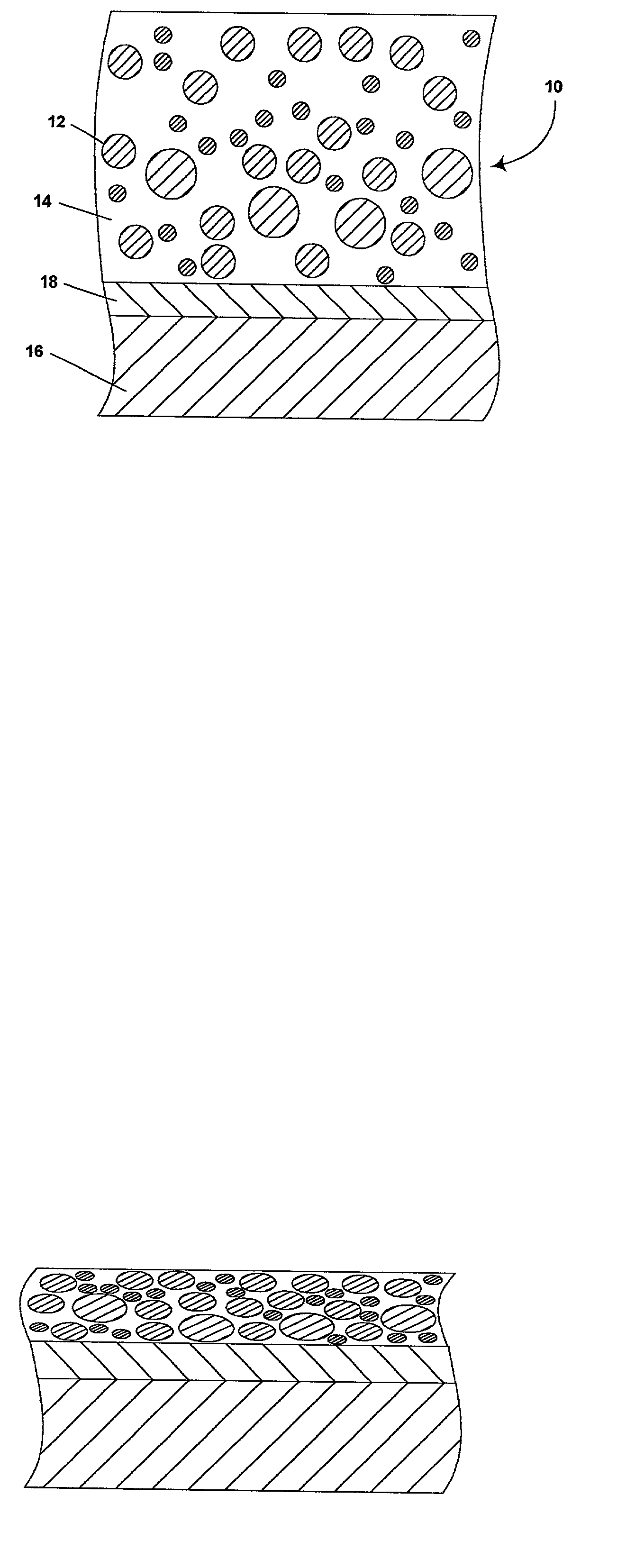
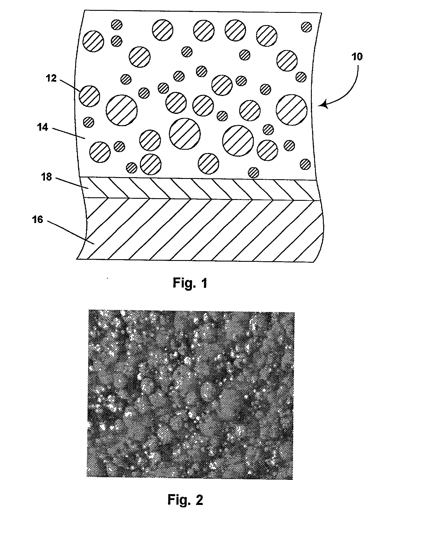
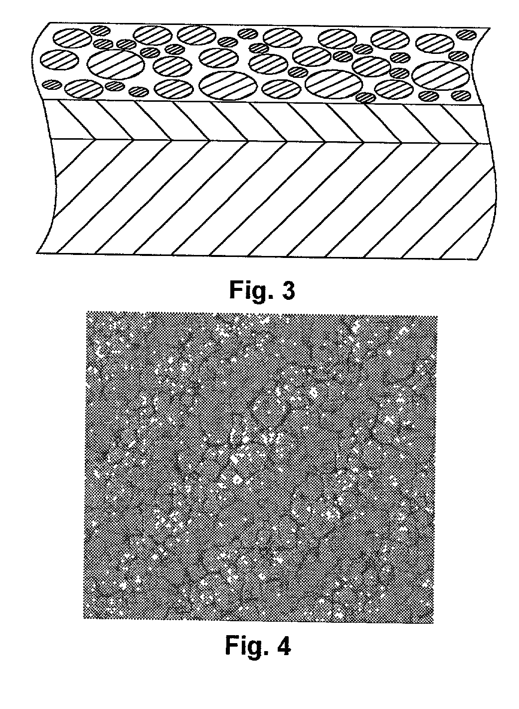
[0054] Example 1 was repeated except that the internal phase contained 17 percent by weight white particles and 1.8 percent by weight black particles, and that only 59.5 g of internal phase was added to 200 g of gelatin solution in order to keep the volume ratio of the two phases the same as in Example 1. Also, a 5 mil (127 .mu.m) gap was used with the draw down bar to produce a dried electrophoretic medium approximately 41 .mu.m thick and having a maximum droplet size of about 35 .mu.m.

[0055] In order to test the switching properties of the medium, the medium was vacuum laminated at 60.degree. C. to a ITO-coated polyester using NeoRez R-9320 urethane binder (available commercially from Zeneca Resins, Wilmington, Del.; NeoRez is a Registered Trade Mark) as the lamination adhesive; the lamination adhesive layer in the final structure was 79 .mu.m thick. A 30 V square wave form (500 msec at 30 V followed by 500 msec at 0 V) was applied to the electrodes. The electrophoretic medium swi...


PUM

PropertyMeasurementUnit
Fractionaaaaaaaaaa
Percent by massaaaaaaaaaa
Fractionaaaaaaaaaa

Abstract

A two-phase electrophoretic medium comprises a continuous phase and a discontinuous phase. The discontinuous phase comprises a plurality of droplets, each of which comprises a suspending fluid and at least one particle disposed within the suspending fluid and capable of moving through the fluid upon application of an electric field to the electrophoretic medium. The continuous phase surrounds and encapsulates the discontinuous phase. The discontinuous phase comprises at least about 40 percent by volume of the electrophoretic medium.

Description

CRASS REFERENCE TO RELATED APPLICATIONS[0001] This application claims priority from Provisional Applications Serial Nos. 60 / 277,079 filed Mar. 19, 2001 and 60 / 277,391 filed Mar. 19, 2001.REFERENCED-APPLICATIONS[0002] This application is related to Application Ser. No. 09 / 493,635, filed Jan. 28, 2000, which is a divisional of Application Ser. No. 09 / 141,105 filed Aug. 27, 1998 (now U.S. Pat. No. 6,067,185), which in turns claims priority from thirty earlier applications. The entire contents of these thirty-four prior applications are herein incorporated by reference.BACKGROUND OF INVENTION[0003] This invention relates to a electrophoretic medium and to a process for the production of this medium. More specifically, this invention relates to a two-phase electrophoretic medium which comprises a discontinuous phase containing electrophoretically-mobile particles and a continuous phase essentially free from such particles.[0004] Electrophoretic displays have been the subject of intense r...

Claims


Application Information

Patent Timeline
IPC IPC(8): G02F1/167
CPCG02F1/167
Inventor PAOLINI, RICHARD J. JR.MILLER, DAVID D.COMISKEY, BARRETT
Owner E INK CORPORATION
Why Eureka
Try Eureka