Optical fiber coupler and an optical fiber coupler incorporated within a transceiver module

Inactive Publication Date: 2002-09-19
JDS UNIPHASE CORP
View PDF0 Cites 35 Cited by
  • Summary
  • Abstract
  • Description
  • Claims
  • Application Information

AI Technical Summary

Benefits of technology

0006] It is an object of the invention to couple a pair

Problems solved by technology

This handling and positioning of a relatively long pigtail of optical fiber seriously exposes the optical fiber pigtail to damage and breakage, because the optical fiber is very fragile and cannot be sharply bent.
Any rough handling or sharp bending of an optical fiber, during manufacture and assembly will cause cracking or breakage of the optical fiber, thereby rendering the optical sub-assembly useless and neces

Method used


Image

  • Optical fiber coupler and an optical fiber coupler incorporated within a transceiver module
  • Optical fiber coupler and an optical fiber coupler incorporated within a transceiver module
  • Optical fiber coupler and an optical fiber coupler incorporated within a transceiver module

Examples


Embodiment Construction

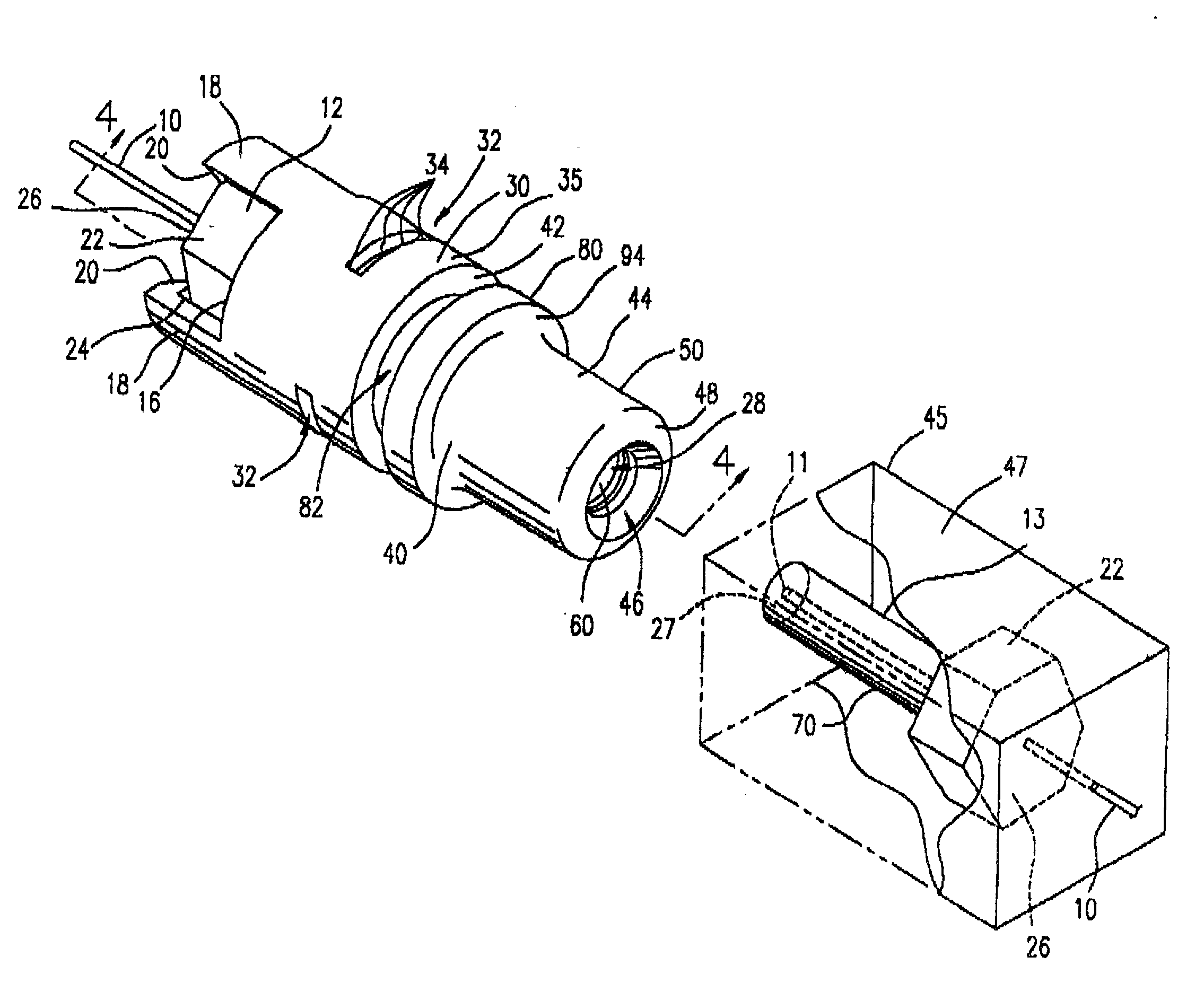
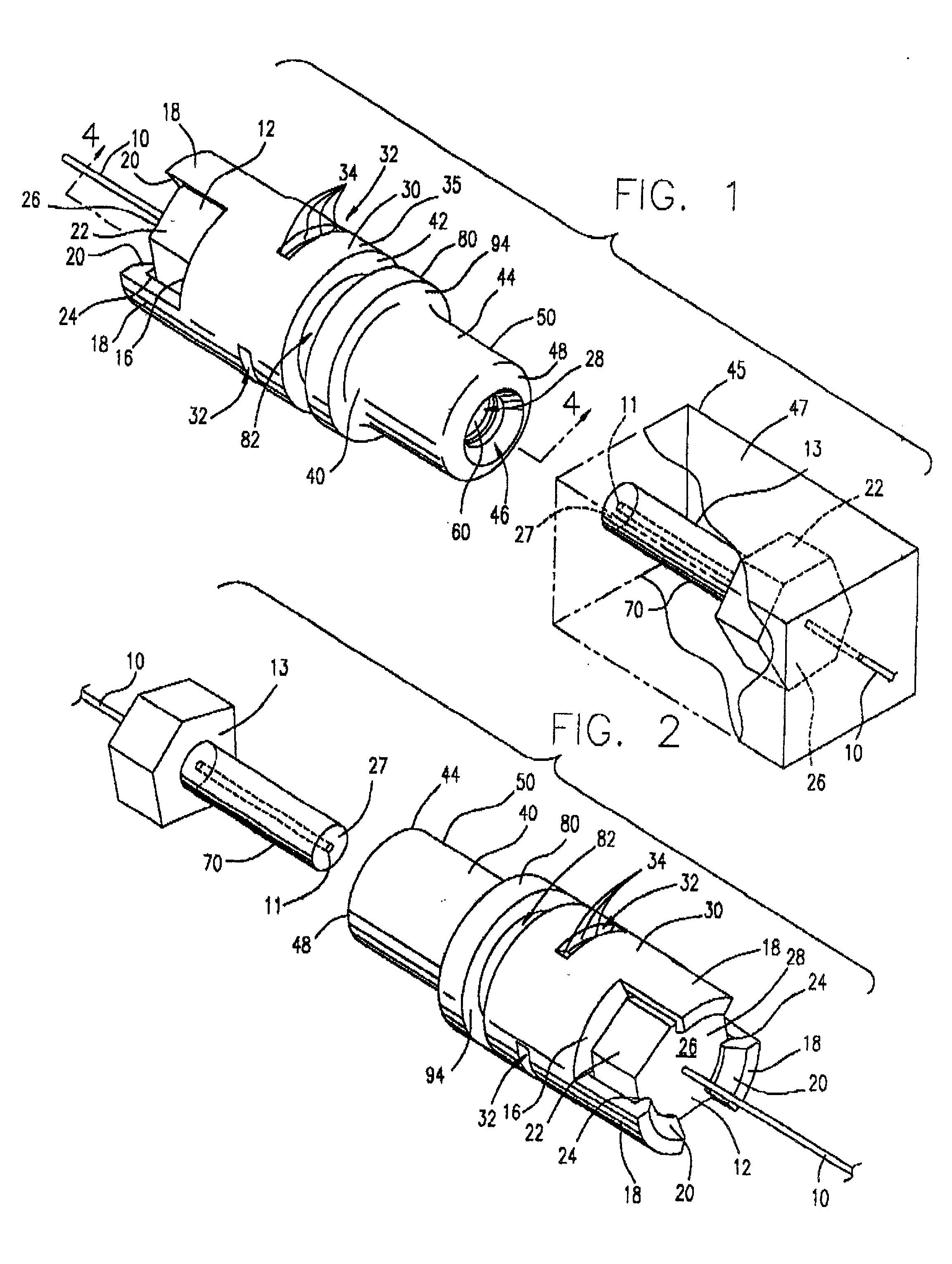
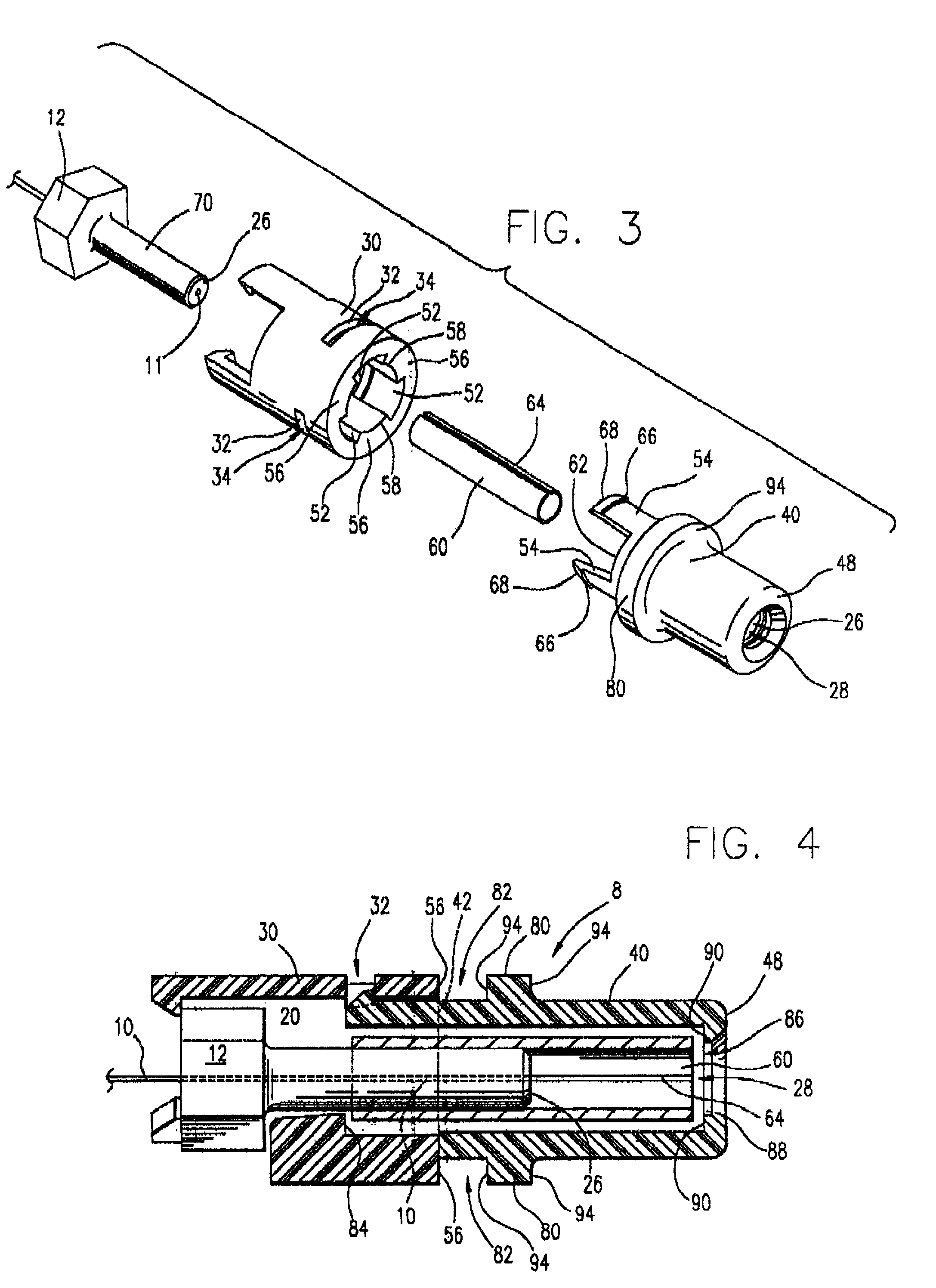
[0023] Referring initially to FIGS. 1 and 2, the coupler 8 of the invention is illustrated in elevated isometric views from each end thereof.

[0024] An optical fiber 10 is shown inserted into a ferrule 12. The ferrule 12 is attached to the optical fiber 10 either by potting the optical fiber 10 within the ferrule 12 with an epoxy or other hard setting potting compound to fix the optical fiber 10 relative to ferrule 12. If the optical fiber 10 is metal clad, the ferrule 12 and the clad optical fiber 10 may be soldered. Polished end face 11 of optical fiber 10 is preferably flush with the end face 26 of the ferrule 12 and the end face and the optical fiber are slightly rounded into a convex end face 26. The ferrule 12 is shown inserted into a first coupler member 30.

[0025] A plurality of latch retainers 18 are formed on one end 16 of the first coupler member 30. Latch retainers 18 each have tapered surfaces 20 which converge and form camming surfaces 20 so they engage the enlarged port...


PUM


Abstract

A coupler to interconnect or couple optical fibers together and position ends of the optical fibers juxtaposed with each other, additionally includes a captive split tubular alignment sleeve to accept ferrules on ends of optical fibers to be aligned and coupled. The coupler may be incorporated into an opto-electronic module, captured, and then held against normal forces of connecting and disconnecting the optical fiber. A short optical fiber extends from the coupler through a wall of an enclosure and is terminated adjacent an opto-electronic device to carry optical signals for transmission or reception of optical signals. This coupler may be further used to splice or interconnect optical fibers, in temporary connections or splices, without fusing the glass of the fibers.

Description

[0001] This invention relates to the field of optical signal transmission and reception over optical fibers and, more specifically, to the interconnection of optical fibers within a transceiver module with optical fibers and connectors of an optical fiber cable.[0002] In order to interconnect network optical fibers to opto-electronic devices, such as transmit optical sub-assemblies or receive optical sub-assemblies of a computer or server, a typical technique uses a relatively, long optical fiber or pigtail with an interfacing connector on one end thereof. The optical fiber and connector are typically assembled with the optical fiber routed to an opto-electronic device which either produces or receives an electronically generated and controlled optical signal. The assembled device is installed into a host device, and the interfacing connector then is positioned and fixed to the host device.[0003] This handling and positioning of a relatively long pigtail of optical fiber seriously e...

Claims


Application Information

Patent Timeline
IPC IPC(8): G02B6/38
CPCG02B6/3821G02B6/3897G02B6/421G02B6/4246G02B6/4272G02B6/426G02B6/4269
Inventor GAIO, DAVID P.HOGAN, WILLIAM K.
Owner JDS UNIPHASE CORP
Why Eureka
Try Eureka