Liquid filter construction and methods

a technology of liquid filter and construction method, which is applied in the direction of filtration separation, lubricant mounting/connection, separation process, etc., can solve the problems of filter head not being spun off from the filter head, system strength not optimized, and failure typically occurring at the rolled lock joint, so as to improve burst strength and impulse fatigue strength, the effect of eliminating the use of a roll or lock seam

a technology of liquid filter and construction method, which is applied in the direction of filtration separation, lubricant mounting/connection, separation process, etc., can solve the problems of filter head not being spun off from the filter head, system strength not optimized, and failure typically occurring at the rolled lock joint, so as to improve burst strength and impulse fatigue strength, the effect of eliminating the use of a roll or lock seam

US20020139735A1Inactive Publication Date: 2002-10-03DONALDSON CO INC

Image

  • Liquid filter construction and methods
  • Liquid filter construction and methods
  • Liquid filter construction and methods

Examples


Embodiment Construction

0 0 0 0 B 0 120 35-55 45 C 30 150 80-100 90 D 90 210 125-145 135 E 120 270 170-190 180 F 180 330 215-235 225 G 200 400 260-280 270 H 210 410 305-325 315 I 500 800 665-685 675 J 510 810 710-730 720

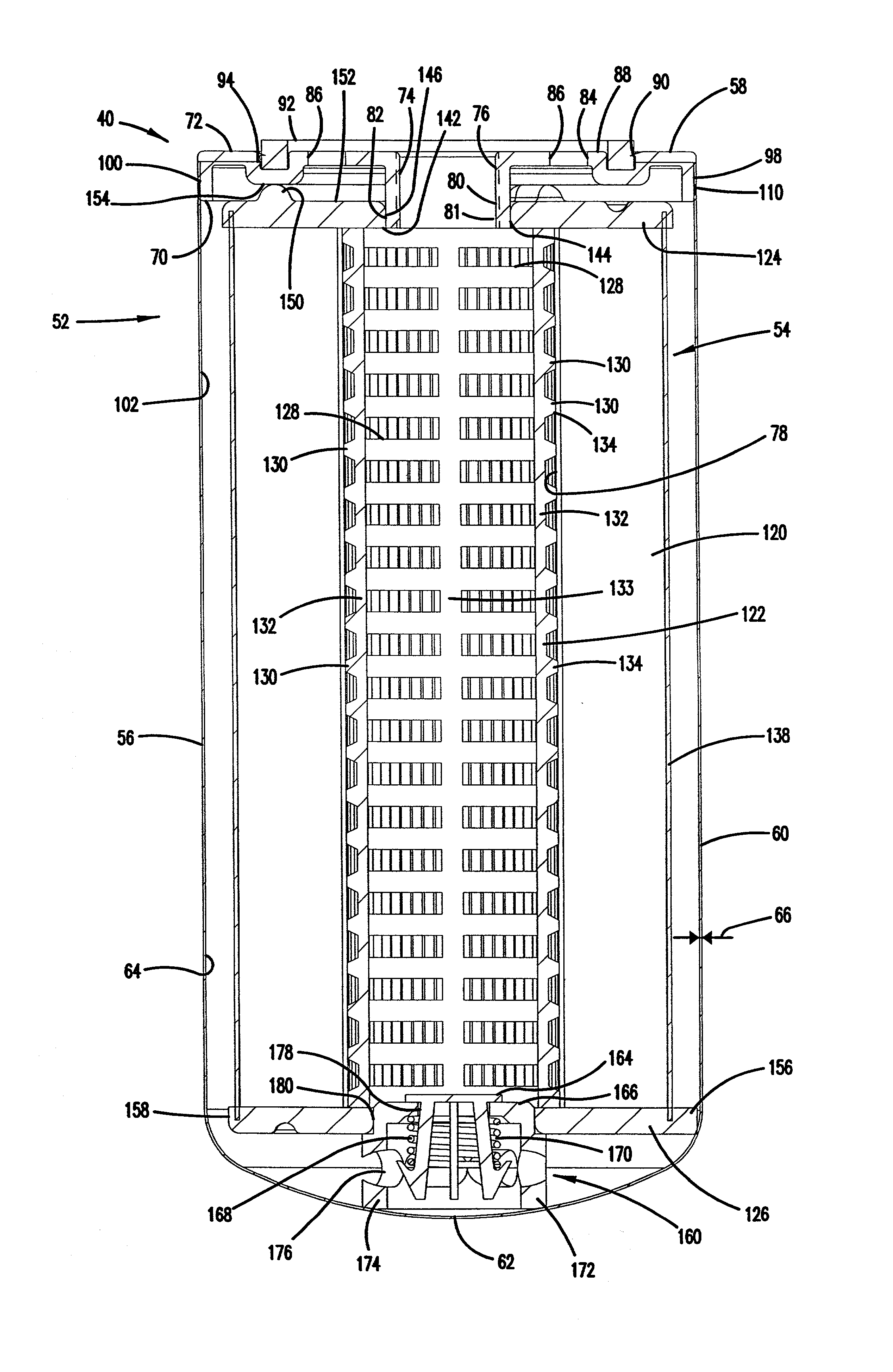
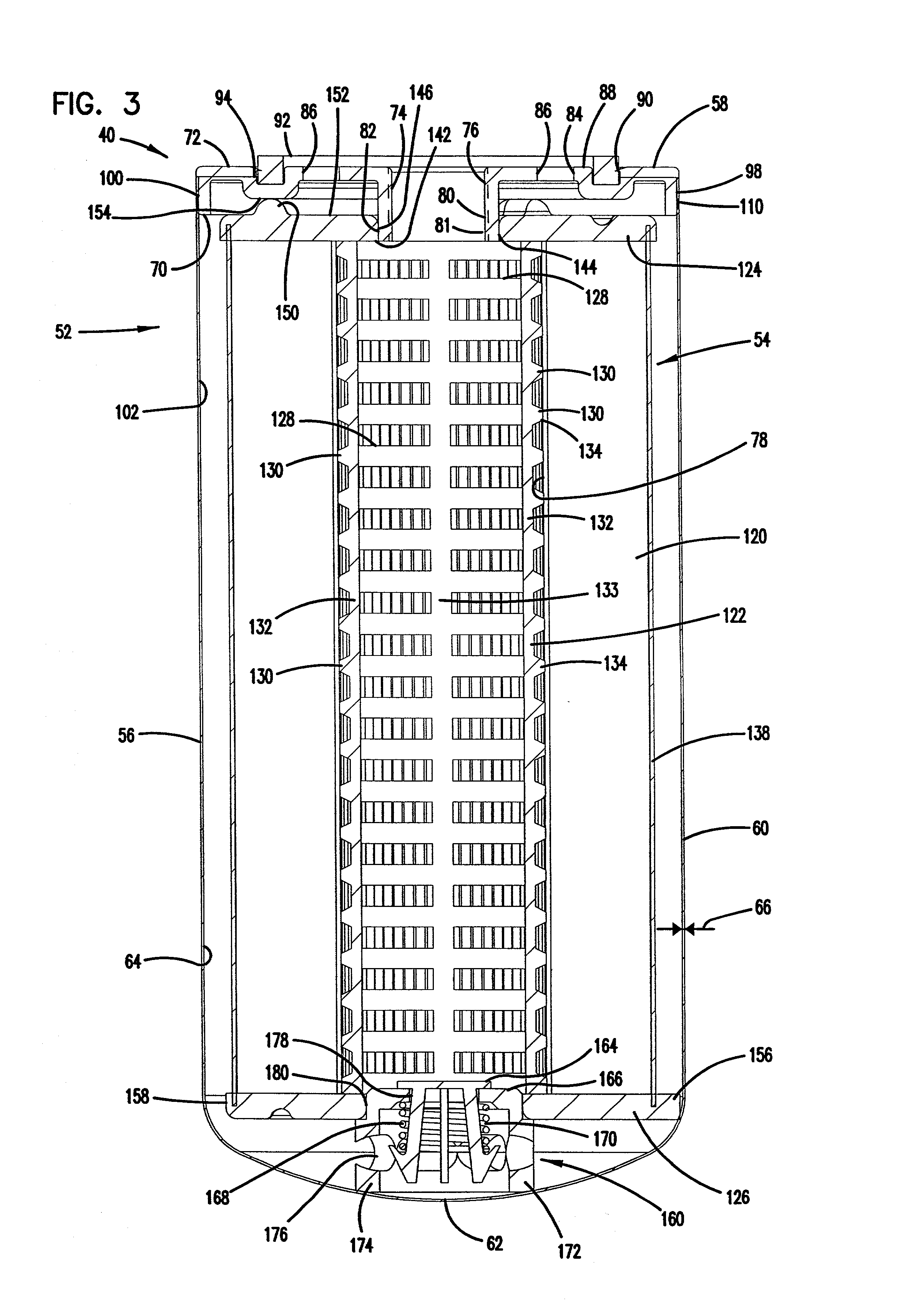
[0101] In general, it should be appreciated from the above discussion that the number of tacks applied between the baffle plate 58 and can 56 can vary between at least 1 tack, no more than about 16 tacks, and typically about 2-8 tacks. Preferably, the processes will have the tacks evenly spaced. In preferred processes, the tacks are formed by varying the power between a low power (on the order of 100 watts), up to a power sufficient to form a tack or spot weld at a fast enough speed (in these examples, at least 3 kW and a speed of at least 300 inches / minute, typically, at least 400 inches / minute). The power variance can be in the form of a saw-tooth wave, a square wave, a sine wave, and other such patterns. In preferred processes, after the plurality of stitches or tacks is applied, there w...


PUM

PropertyMeasurementUnit
thicknessaaaaaaaaaa
thicknessaaaaaaaaaa
pressuresaaaaaaaaaa

Abstract

Liquid filter constructions include a baffle plate secured to a can, by way of laser welding. A filter element is operably oriented within the interior of the can. The filter element includes a first end cap and a media pack secured to the first end cap. In some embodiments, the first end cap radially abuts an outer, annular surface of a tubular member of the baffle plate to form a radially directed seal between the first end cap and the tubular member. Liquid filter constructions of this type have a burst strength between 500-800 psi (about 3.4-5.5 MPa), along a longitudinal section of the can wall. Constructions of this type eliminate a roll or lock seam, an inner gasket, an inner compressive spring, and a gasket retainer. Systems for using liquid filters are described herein. Methods of constructing and using these types of filter arrangements are also described.

Description

[0001] This disclosure relates to fluid filters including their construction and use. In particular, this disclosure concerns liquid filters to clean contaminants from fluid systems such as engine and transmission lubrication systems, engine fuel systems, and hydraulic systems.[0002] Certain types of fluid filters, for example oil or lube filters, fuel filters, or hydraulic fluid filters, operate to remove substantial amounts of particulate material from liquid flow, typically in a circulating environment.[0003] Such filters generally include a filter element within a drawn, relatively thin, cylindrical metal housing and a stamped metal baffle or cover plate at the open end of the housing. Typically, there is a gasket retainer projection welded to the cover plate, and the gasket retainer is secured to the housing by a roll or lock seam. A central threaded opening is provided in the cover plate for spinning the filter onto a threaded stud of a mounting base or filter head.[0004] Flui...

Claims


Application Information

Patent Timeline
03 Oct 2002
Publication
US20020139735A1
IPC
B01D27/00
CPC
B01D27/005; B01D2201/291; B01D2201/302; B01D2201/304; B01D2201/4046; B01D27/08; B01D27/103
Inventors
STENERSEN, EIVIND; HARDER, DAVID B.