Thin-film piezoelectric bimorph element, mechanical detector and inkjet head using the same, and methods of manufacturing the same

a piezoelectric bimorph element and mechanical detector technology, applied in the direction of mechanical vibration separation, acceleration measurement using interia forces, instruments, etc., can solve the problems of insufficient durability, difficulty in uniform control of the thickness and hardening of the adhesive agent, and sensitivity variations of the conventional piezoelectric bimorph elemen

Inactive Publication Date: 2002-10-17
PANASONIC CORP
View PDF12 Cites 63 Cited by
  • Summary
  • Abstract
  • Description
  • Claims
  • Application Information

AI Technical Summary

Problems solved by technology

However, since it is extremely difficult to uniformly control the thickness and hardening of an adhesive agent, the conventional piezoelectric bimorph element has the problem of sensitivity variations due to non-uniform adhesion.
Over a prolonged period of use, the piezoelectric members may peel off the metal plate, which leads to the problem of insufficient durability.
Furthermore, the thickness of the piezoelectric members cannot be reduced excessively since a certain degree

Method used


Image

  • Thin-film piezoelectric bimorph element, mechanical detector and inkjet head using the same, and methods of manufacturing the same
  • Thin-film piezoelectric bimorph element, mechanical detector and inkjet head using the same, and methods of manufacturing the same
  • Thin-film piezoelectric bimorph element, mechanical detector and inkjet head using the same, and methods of manufacturing the same

Examples


embodiment 1

[0061] Embodiment 1

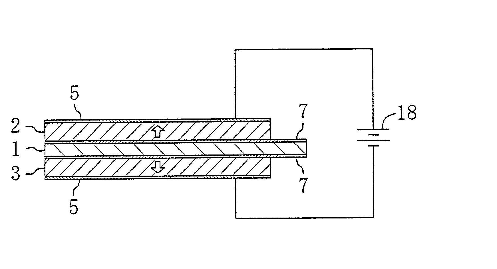
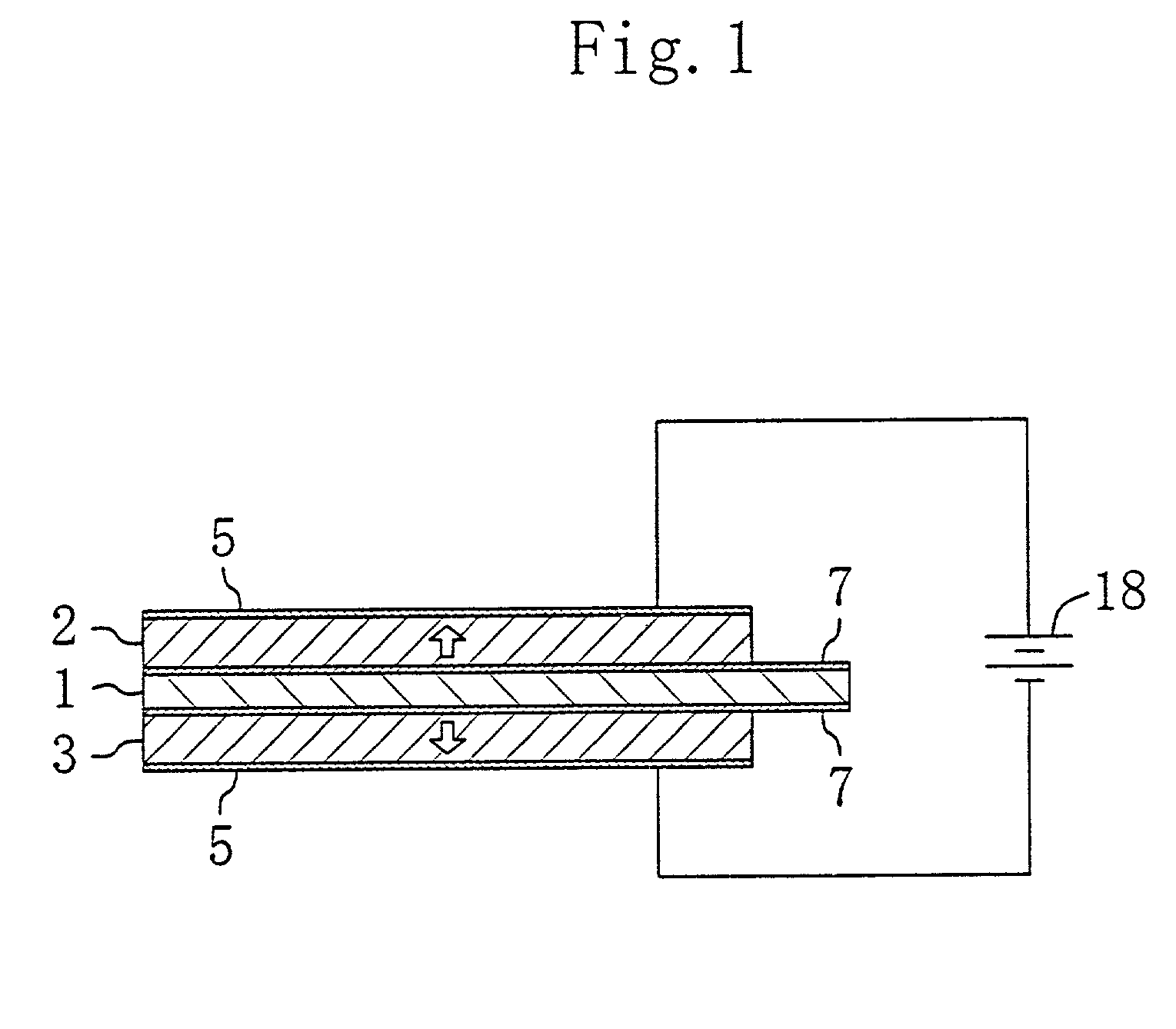
[0062] FIG. 1 shows a thin-film piezoelectric bimorph element according to Embodiment 1 of the present invention. The thin-film piezoelectric bimorph element comprises a metal thin plate 1 made of stainless steel and having a thickness of 50 to 200 .mu.m (preferably 50 to 100 .mu.m).

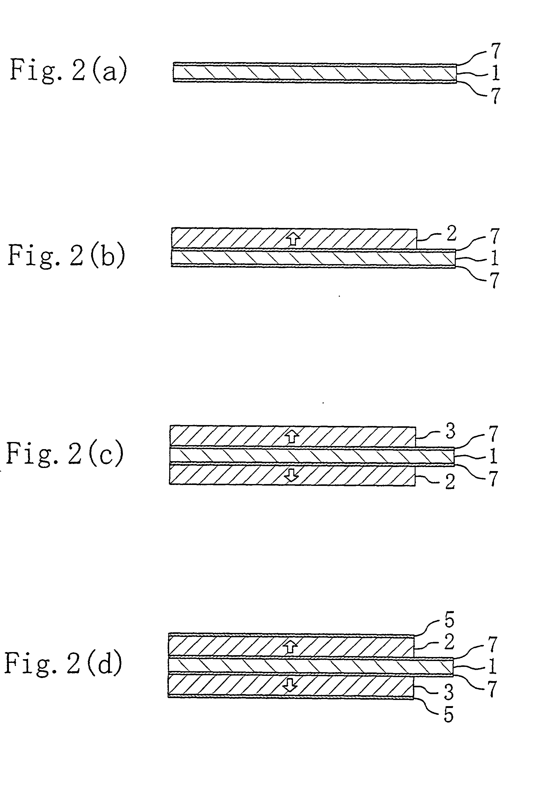
[0063] A first piezoelectric thin film 2 is provided on one of the both surfaces (upper surface) of the metal thin plate 1 which are in opposing relation to each other along the thickness thereof with a diffusion preventing film 7 interposed therebetween, which will be described later, while a second piezoelectric thin film 3 is provided on the other of the both surfaces (lower surface) of the metal thin plate 1 which are in opposing relation to each other along the thickness thereof with another diffusion preventing film 7 interposed therebetween. The first and second piezoelectric thin films 2 and 3 having equal thicknesses are formed by sputtering on the both surfaces of the metal t...

embodiment 2

[0086] Embodiment 2

[0087] FIG. 4 shows Embodiment 2 of the present invention (in each of the following embodiments, the detailed description of the same components as shown in FIG. 1 will be omitted by retaining the same reference numerals), in which each of first and second piezoelectric thin films 2 and 3 has a multilayer structure.

[0088] That is, the first piezoelectric thin film 2 in Embodiment 2 is composed of a plurality of (three in the present embodiment) piezoelectric layers 2a, 2b, and 2c stacked along the thickness of the metal thin plate 1. The piezoelectric layers 2a, 2b, and 2c are constituted to have a piezoelectric constant which decreases gradually with approach toward the metal thin plate 1. Specifically, if the composition of the first piezoelectric thin film 2 is represented by PbZr.sub.xTi.sub.1-xO.sub.3 as described above, the value of X is changed appropriately for each of the piezoelectric layers 2a, 2b, and 2c to change the proportion of Zn to Ti. If the val...

embodiment 3

[0097] Embodiment 3

[0098] FIG. 7 shows Embodiment 3 of the present invention, in which the directions of polarizations of the first and second piezoelectric thin films 2 and 3 are the same. That is, the direction of polarization of the first piezoelectric thin film 2 is from the side opposite to the metal thin plate 1 toward the metal thin plate 1 (downward), which is different from Embodiments 1 and 2.

[0099] After a pair of electrode films 5 are connected to the negative terminal of a power source 18 and a metal thin plate 1 (or diffusion preventing films 7 as electrodes) is connected to the positive terminal thereof, if a voltage is applied between the metal thin plate 1 and each of the electrode films 5, an upward electric field is generated in the first piezoelectric thin film 2, while a downward electric field is produced in the second piezoelectric thin film 3, as shown in FIG. 7. This expands the first piezoelectric thin film 2 and contracts the second piezoelectric thin film...


PUM

PropertyMeasurementUnit
Temperatureaaaaaaaaaa
Thicknessaaaaaaaaaa
Frequencyaaaaaaaaaa

Abstract

To manufacture a compact and high-performance thin-film piezoelectric bimorph element at low cost, first and second piezoelectric thin films (2, 3) are formed by sputtering on the both surfaces of a metal thin plate (1) which are opposing relation to each other along the thickness thereof, while the respective states of polarizations of the first and second piezoelectric thin films (2, 3) are controlled. A pair of electrode films (5) are formed on the respective surfaces of the first and second piezoelectric thin films (2, 3) opposite to the metal thin plate (1).

Description

[0001] 1. Field of the Invention[0002] The present invention relates to a thin-film piezoelectric bimorph element, a mechanical detector and an inkjet head using the same, and methods of manufacturing the same.[0003] 2. Description of the Prior Art[0004] In recent years, research and development has been conducted on a dielectric substance, in particular a ferroelectric substance, as a basic material of a pyroelectric IR detector using a pyroelectric property, a piezoelectric detector (sensor) and a piezoelectric actuator using a piezoelectric property, a nonvolatile memory using polarization inversion, a capacitive element using a high-dielectric-constant property, and the like.[0005] The piezoelectric detector has been used as a mechanical detector for detecting a dynamic amount such as acceleration or pressure by using a "piezoelectric effect," which is the generation of charge from a piezoelectric member as a result of the application of a force to the piezoelectric member. The ...

Claims


Application Information

Patent Timeline
IPC IPC(8): B06B1/06B41J2/055B41J2/045B41J2/14B41J2/16G01P15/08G01P15/09H01L41/08H01L41/09H01L41/113H02N2/00
CPCB41J2/14233B41J2002/14258G01P15/0802G01P15/09H01L41/1132H01L41/094Y10T29/49005Y10T29/49128Y10T29/42Y10T29/49126Y10T29/49004Y10T29/49147Y10T29/49002H10N30/2042H10N30/2047H10N30/302H10N30/076H10N30/00
Inventor FUJII, SATORUKANNO, ISAKUTAKAYAMA, RYOICHIKAMADA, TAKESHI
Owner PANASONIC CORP
Why Eureka
Try Eureka