
Method of varying the ink density of the full tone in offset printing within a rotoary printing machine

a rotary printing machine and offset printing technology, applied in the field of varying the ink density of the full tone in offset printing within the rotary printing machine, can solve the problems of the complexity the inability of the inking unit to regulate the ink supply, and the disadvantage of the ink supply regulation

Inactive Publication Date: 2002-10-24
MANROLANAD AG
View PDF0 Cites 10 Cited by
  • Summary
  • Abstract
  • Description
  • Claims
  • Application Information

AI Technical Summary

Benefits of technology

[0014] The term "tonal value gain" as used herein is therefore the increase in the area coverage from the printing plate to the printed material. The tonal value gain breaks down into two components, i.e., an optical one and a geometric one. The optical component is brought about by immigration of light in the printing material (light capture) from the uncovered areas to the covered areas. The geometric component, which is relevant especially for plate the method according to the invention, is brought about as a result of squeezing effects at the ink transfer points from the printing plate to the printing material or, in electrophotography, by tonal clouds around the actual image points. As a result of this effect, the area on the printing plate not covered by ink, i.e., the uncovered area, is reduced geometrically from the edges of the covered area during transfer of the ink to the printing material.

Problems solved by technology

However, the ability of the inking unit to regulate the ink supply has disadvantages both with regard to the expenditure on control and also with regard to the complexity of the inking unit which results from this.
The regulation of the ink supply also has a disadvantage with regard to the desired freedom of reaction of various ink uptake rates on following printed copies.
However, this form of the inking unit permits only very restricted regulation of the ink supply.

Method used


Image

  • Method of varying the ink density of the full tone in offset printing within a rotoary printing machine
  • Method of varying the ink density of the full tone in offset printing within a rotoary printing machine
  • Method of varying the ink density of the full tone in offset printing within a rotoary printing machine

Examples


Embodiment Construction

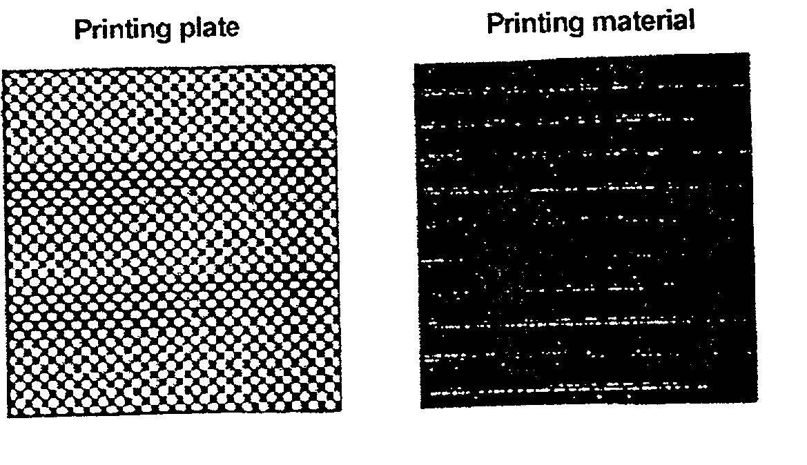
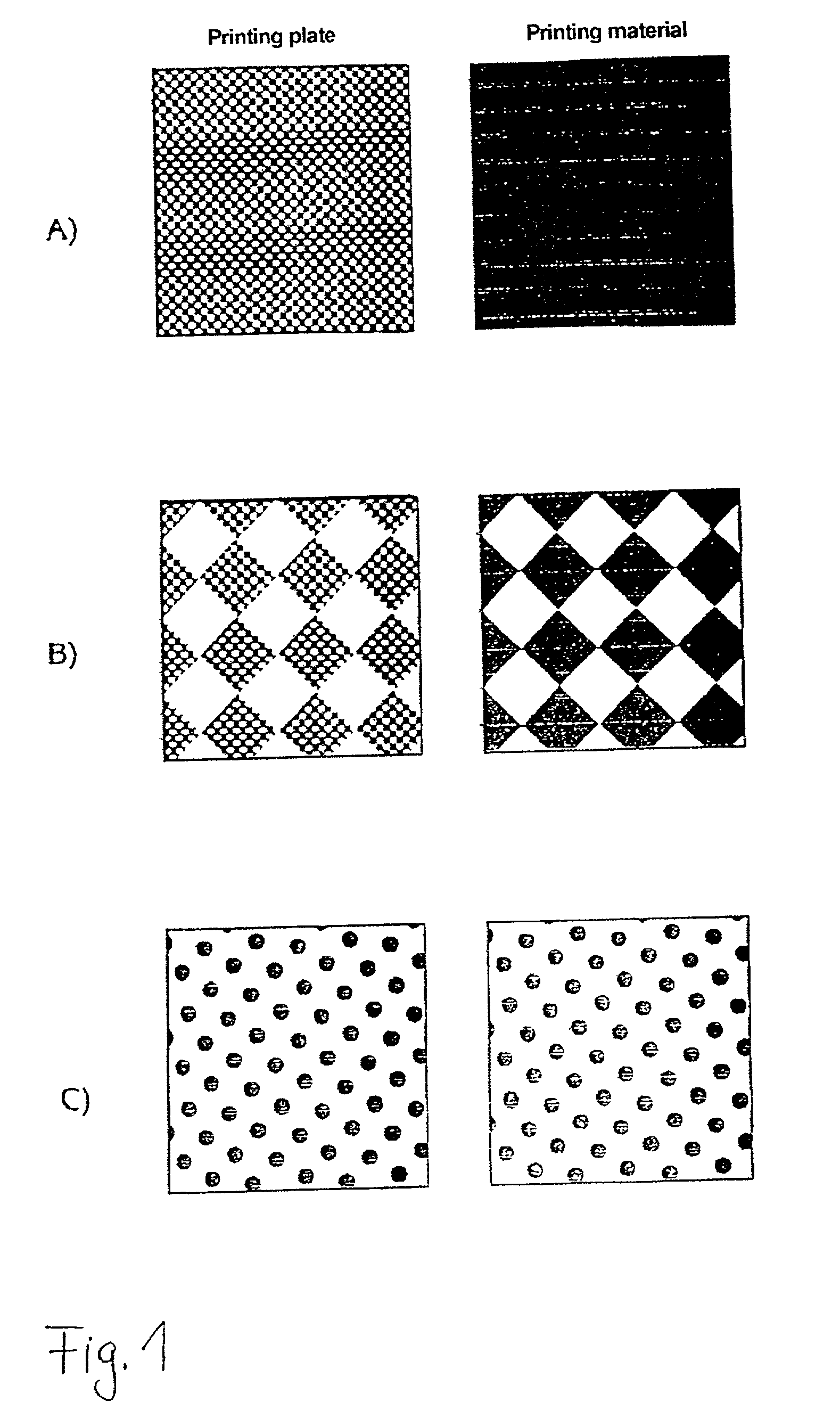
[0022] FIG. 1A shows the effects of tonal value gain for the case of a solid tone. The pattern of the printing plate in FIG. 1A becomes fuller on the printed material. The basic raster is superimposed on a microraster of 50%, that is to say only about 50% of the amount of ink of a fully covered full tone is picked up. The microraster does not appear on the printing material as a result of the geometric tonal value gain. The result is a full tone with a substantially reduced density.

[0023] This procedure can also be continued in the area of raster tones in which the basic raster is a half tones, as shown schematically by FIG. 1B. It is, of course, possible to dispense with a microraster in the region of highlights according to FIG. 1C or to set a 0% tonal value reduction. In addition, a gentle transition with a large reduction at high tonal values and a lower to no reduction at small tonal values is conceivable.

[0024] A fact which assists this effect is, moreover, that the ink layer ...


PUM


Abstract

A method of varying the ink density of the full tone in printing within a rotary printing machine with an ink application system which can provide a constant quantity of ink which, in spite of constant ink supply from the inking unit, permits control of the full-tone density or adaptation of the raster tonal values in the print. The method includes setting the binary image on a printing plate. A basic raster of raster points, which determines the area coverage of the binary image, is produced on the printing plate for the variable-area image information. The basic raster is then superimposed on a fine microraster in such way that the area coverage of the basic raster is reduced by a percentage which can be set between 0% and 100%.

Description

[0001] 1. Field of the Invention[0002] The present invention relates to a method of varying the ink density of the full tone in offset printing within a rotary printing machine.[0003] 2. Description of the Related Art[0004] In digital printing processes, i.e., processes for producing printing plates in a binary sense, an ink supply is either accepted locally or not. This is the case, for example, in planographic printing or offset printing. The ink density of uninterrupted ink layers is the full tone characteristic of the ink layer and is controlled by the rate of the ink supply from the ink supply system to the printing plate.[0005] In conventional offset printing, the ink supply and therefore the thickness of the ink layer supplied to the printing plate is regulated via inking zone screws. The printing plate has ink-accepting and ink rejecting regions and picks up the ink in proportion to the amount supplied only in those regions that are ink-accepting. The amount of ink picked up...

Claims


Application Information

Patent Timeline
Patent Type & Authority Applications(United States)
IPC IPC(8): B41C1/05B41C1/10B41F33/00B41M1/00B41M1/04B41M1/06B41M1/10
CPCB41C1/05B41C1/10B41F33/0027B41P2233/51B41M1/04B41M1/06B41M1/10B41M1/00B41N1/12
Inventor WEICHMANN, ARMIN
Owner MANROLANAD AG
Learn More