Fluid Separate conduit cartridge

a technology of separate conduit and conduit cartridge, which is applied in the direction of fluid speed measurement, optical light guide, chemical/physical/physico-chemical microreactor, etc., can solve the problems of inability to effectuate column performance assessment, deterioration of the packed bed and the bonded phase of the column, and the failure of the column itself to store the performance information, etc., to save frustration and useless data acquisition.

Inactive Publication Date: 2002-10-24
PROTASIS CORP
View PDF13 Cites 68 Cited by
  • Summary
  • Abstract
  • Description
  • Claims
  • Application Information

AI Technical Summary

Benefits of technology

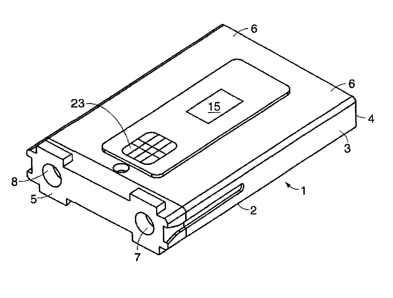
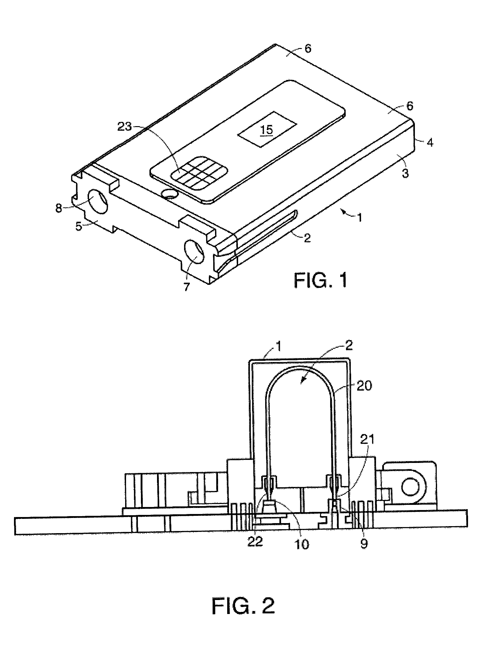
[0012] In accordance with additional aspects, a fluid separation conduit cartridge comprising at least a housing unit and a separation conduit that is potted is disclosed. As used here potted refers to surrounding, e.g. enveloping, encasing, enclosing, and the like, one or more components of the cartridge with a potting compound. The potting compound prevents movement of the components within the conduit cartridge and provides protection to any sensitive components, e.g. a memory unit, within the cartridge. In certain embodiments, the potting compound envelops the conduit cartridge and allows the cartridge to withstand higher pressures without rupturing, fracturing or leaking. Exemplary potting compounds include but are not limited to thermoset and thermoplastic polymers, e.g., epoxies, glass filled epoxies, metal filled epoxies, carbon-filled epoxies, and the like. In certain embodiments, the fluid separation conduit cartridge may comprise a housing unit, one or more memory units, one or more connectors, and a potted fluid separation conduit. The potting compounds typically have no effect on the memory unit or any other components within the housing unit or attached to the housing unit. That is, the memory unit may be integrated into the housing unit of the cartridge and the potting compounds can be disposed in the housing unit to encapsulate the fluid separation conduit and the memory unit without adversely affecting operation of the conduit cartridge. The potting compound can be disposed prior to packing the conduit with a packing material or after packing the conduit with a packing material. In certain embodiments, the conduit cartridge comprises a housing unit, one or more connectors, a potted conduit, and a memory unit. In yet other embodiments, the conduit cartridge comprises a housing unit, one or more connectors and a potted conduit but no memory unit. One skilled in the art, given the benefit of this disclosure, will be able to choose components for incorporation into the conduit cartridges disclosed here suitable for an intended use.
[0015] Certain preferred embodiments of the fluid separation conduit cartridge disclosed here provide useful information as to the cartridge's performance that is critical in both Good Manufacturing Practice and Good Laboratory Practice settings. Damaged conduit cartridges can be detected early, thereby saving on both frustration and useless data acquisition. Full traceability of the conduit cartridge throughout its lifetime is available to the end-user or any other interested party with appropriate access capabilities.

Problems solved by technology

Through continued usage, the column's packed bed and the bonded phase deteriorate.
Apart from performing a chromatographic run with known analytes, assessment of the column cannot be effectuated.
Currently, columns themselves lack the ability to store their performance information which can be of great value.

Method used


Image

  • Fluid Separate conduit cartridge
  • Fluid Separate conduit cartridge
  • Fluid Separate conduit cartridge

Examples


example 1

[0047] An example of a fluid separation conduit cartridge interfaced with an analytical system, e.g. a chromatography system, is shown in FIG. 9. The analytical system typically is positioned within an end-user's facility for automated analyses. That is, the analytical system may be positioned near, or in-line, e.g. within the sample flow itself, such that analysis of samples may occur automatically, e.g. using auto-samplers, auto-injectors, and the like, or to facilitate rapid analysis of samples, e.g. samples during a process by an operator at an end-user's facility. For example, the system can be configured for analysis at specified intervals, e.g. every minute, hour, day, etc., such that continuous monitoring of a process can be performed with little or no user input. That is, the system can be configured to run a chromatographic method at a specified time interval without additional input from an operator. Referring to FIG. 9, the analytical system 400 typically comprises a con...

example 2

[0056] An additional example of a fluid separation conduit cartridge interfaced with an analytical system is shown in FIG. 12. The analytical system 500 comprises a fluid separation conduit cartridge 502, e.g. a cartridge operative to perform capillary liquid chromatography, a graphical user interface 504, and buffer cassettes 506. The graphical user interface can be used to program the system and / or the fluid separation conduit cartridge for a specific method, e.g. a specific solvent gradient, run time, flow rate, and the like. As discussed above, the graphical user interface can be omitted in embodiments where the conduit cartridge is operative to program the system, e.g. where the conduit cartridge comprises an analytical method in a memory unit, for example. The buffer cassettes are equivalent to solvent reservoirs. That is, the buffer cassettes may be loaded with any suitable mobile phase needed to perform a chromatographic method, for example. Preferably, the mobile phases are...


PUM

PropertyMeasurementUnit
internal diameteraaaaaaaaaa
inner diameteraaaaaaaaaa

Abstract

A fluid separation conduit cartridge comprising a fluid separation conduit is disclosed. In certain embodiments the fluid separation conduit is potted to provide operation at increased pressures. In other embodiments, the fluid separation conduit cartridge has one or more memory units. The memory units are operative to store data such as, for example, cartridge usage and test results.

Description

CROSS-REFERENCED APPLICATIONS[0001] This application claims priority to commonly assigned U.S. Patent Application No. 60 / 239,010 titled "Microfluidic Substrate Assembly and a Method for Making Same" and filed on Oct. 6, 2000, commonly assigned U.S. Patent Application No. 60 / 239,063 titled "Liquid Separation Column Smart Cartridge" and filed on Oct. 6, 2000, commonly assigned U.S. Patent Application No. 60 / 238,805 titled "Liquid Separation Column Smart Cartridge with Encryption Capability" and filed on Oct. 6, 2000, and commonly assigned U.S. Patent Application No. 60 / 238,390 titled "Microfluidic Substrate Assembly and a Method for Making Same" and filed on Oct. 6, 2000, the entire disclosure of each of which is hereby incorporated herein by reference for all purposes.FIELD OF INVENTION[0002] Embodiments of this invention are directed to a fluid separation conduit cartridge. More particularly, embodiments of this invention are directed to a fluid chromatography conduit cartridge comp...

Claims


Application Information

Patent Timeline
Patent Type & Authority Applications(United States)
IPC IPC(8): B01J19/00B01L3/00B81B1/00G01N27/447G01N30/24G01N30/60G01N30/88G01N35/00H04L9/32
CPCB01J19/0093Y10T436/25375B01L3/545B01L2200/027B01L2200/10G01N27/44704G01N30/24G01N30/6026G01N30/6034G01N30/6091G01N30/6095G01N30/88G01N35/00732G01N2030/8804G01N2030/8881Y10T29/49826Y10T436/255B01L3/502715
Inventor STRAND, DAVIDANTOCCI, JOEMYERS, PETER
Owner PROTASIS CORP
Why Eureka
Try Eureka