System and method for verifying error detection/correction logic

a technology of error detection and logic, applied in the field of error detection systems, can solve problems such as component failures, errors in transmitted or stored data, and errors in electrical systems

Inactive Publication Date: 2002-10-24
ORACLE INT CORP
View PDF9 Cites 58 Cited by
  • Summary
  • Abstract
  • Description
  • Claims
  • Application Information

AI Technical Summary

Problems solved by technology

Errors in transmitted or stored data may be caused by transient conditions in a system.
For example, some errors may be caused by cross talk or noise.
Component failures are another common source of error in electrical systems.
Faulty components may include faulty memory chips or faulty data paths provided between devices of a system.
For example, faulty data paths may result from faulty pins, faulty data traces, or faulty wires.
The error detection / correction logic used to encode or decode data according to a particular error code may itself be susceptible to failure or errors.
However, tests for error detection / correction logic tend to input a large number of test values into the logic being tested, and as a result, the verification may take a significant amount of time to perform.
Furthermore, even though large numbers of test values may be used, these test values may not be selected to thoroughly test each component of the error detection / correction logic, and thus the tests may not provide a complete verification of the device being tested.

Method used


Image

  • System and method for verifying error detection/correction logic
  • System and method for verifying error detection/correction logic
  • System and method for verifying error detection/correction logic

Examples


Embodiment Construction

[0032] Before describing various embodiments of a method and system for testing error detection / correction logic, several exemplary systems that may include error detection / correction logic and an embodiment of a tester for such error detection / correction logic will be described.

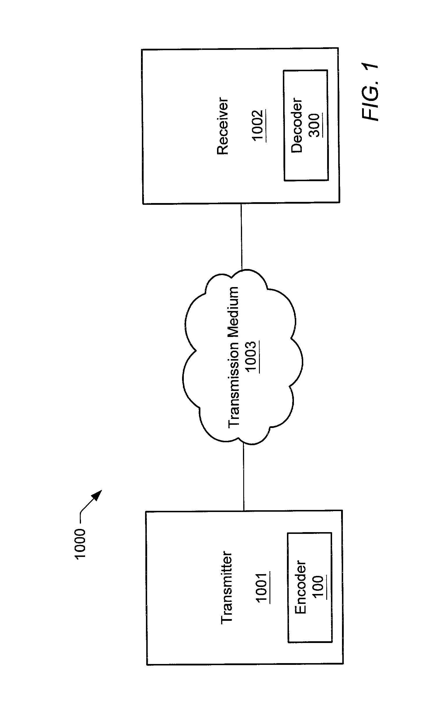
[0033] FIG. 1 shows one embodiment of a communication system 1000 that may include an error code encoder 100 and an error code decoder 300. Communication system 1000 may include a transmitter 1001 and a receiver 1002. Transmitter 1001 may be configured to encode data into a code word using encoder 100. The code word may be transmitted to receiver 1002 via transmission medium 1003. Receiver 1002 may receive the transmitted code word. Using decoder 300, receiver 1003 may extract the original data bits sent by transmitter 902 and detect whether any errors occurred during transmission. If a single-bit error occurred in a data bit, decoder 907 may correct the erroneous bit. If the error code being used is a SECDE...


PUM


Abstract

A method of testing error correction / detection logic may involve providing each of a set of n data bit combinations to the error correction / detection logic. Each data bit combination has n bits, and the n data bit combinations may be created by creating an initial data bit combination whose data bits have the same logical value and then shifting a bit having the opposite value across the initial data bit combination. In response to being provided with the n data bit combinations, the error correction / detection logic generates a set of check bits for each of the n data bit combinations. The set of check bits generated by the error correction / detection logic for each of the n data bit combinations may then be verified.

Description

[0001] 1. Field of the Invention[0002] This invention relates to error detecting systems, and more particularly, to testing error detection / correction logic.[0003] 2. Description of the Related Art[0004] Error codes are commonly used in electronic systems to detect and correct data errors, such as transmission errors or storage errors. For example, error codes may be used to detect and correct errors in data transmitted via a telephone line, a radio transmitter, or a compact disc laser. Error codes may additionally be used to detect and correct errors associated with data stored in the memory or mass storage devices of computer systems. One common use of error codes is to detect and correct errors of data transmitted on a data bus of a computer system. In such systems, error correction bits, or check bits, may be generated for the data prior to its transfer or storage. The check bits may then be transmitted or stored with the data. When the data is received or retrieved, the check b...

Claims


Application Information

Patent Timeline
Patent Type & Authority Applications(United States)
IPC IPC(8): H04L1/00H04L1/24H04L12/24
CPCH04L1/004H04L41/0893H04L1/24H04L1/0057
Inventor BYRD, JAMES M.
Owner ORACLE INT CORP
Why Eureka
Try Eureka