
Hair trimming device with removably mountable components for removal of split ends and styling of hair

a hair trimming and component technology, applied in the field of hair trimming devices with removable mountable components, can solve the problems of hair looking unhealthy and just unfashionable, the method of splitting ends, and the time-consuming process of hair trimming by highly trained stylists or amateurs,

Inactive Publication Date: 2002-10-31
TALAVERA HAIR PROD INC
View PDF0 Cites 12 Cited by
  • Summary
  • Abstract
  • Description
  • Claims
  • Application Information

AI Technical Summary

Benefits of technology

[0022] It is an object of this invention is to create a hair trimmer that can cut a more precise length of hair off the distal end of hair strands.
[0023] Another objective of this invention is to create a device that can be operated by an individual in either hand, and drawing the hair through the serpentine channel in either direction by the means of adjusting the direction of the rotation of the electric motor with a switch.
[0024] Another objective of this invention is to create a device with a means of continuous control of the hair passing through the serpentine channel made possible by the spines on the hair retainer, the spines on the detachable spine units and the teeth on top of the retainer central structure.
[0025] Still, another objective of this invention is to supply a cutter with different length adjustment mechanisms that can guarantee the precise lengths of the trimmed ends of the hair shafts.
[0026] An additional object of this invention is design a unique cutting blade assembly that can cut equally well in either direction of rotation, with a means of flexible resistance on the two shearing surfaces.

Problems solved by technology

However, one vexing problem exists whether the hair on a persons head is being cut by a trained stylist of the individual needing the trim or an amateur, split ends must be removed to keep the hairstyle looking good.
Split ends are a constant and continuous product of combing and brushing of hair and can cause the hair to look unhealthy as well as just unfashionable.
The current method of trimming split ends, either by the highly trained stylist or the amateur involves a time-consuming process.
An errant cut will yield harsh marks, uneven cuts, or other undesired results in the head of hair of the person receiving the hair cut.
Split ends are an especially vexing problem in the case of hair shoulder length and longer in styles worn by women and men.
Because of the varying length of the strands of hair involved from the ears down to the shoulders or below, it is especially time consuming to try and trim only the ends of the hair, a very small relatively equal amount, while not accidentally cutting long adjacent strands.
This process is made even harder when the style of cut is tapered through the length and just the short ends require cutting maintaining the tapered style.
It is virtually impossible for a person with long hair to trim the split ends themselves as cutting the split ends of the hair on the back of one's head, using a mirror and scissors is a task fraught with peril.
One slip and the hairstyle could be ruined by cutting some long strands of the hair laying adjacent to the distal split ends on shorter hair shafts.
While many of these devices address the issue of cutting hair and styling it, few devices address the issue of split ends on the distal ends of the hair and removing only a predetermined short length of the unhealthy distal ends.
This can be very tedious if not an impossible task with the hundreds of hairs on an individuals' head.
However, Smith requires many adjustments by the individual using the device and it is intended to cut long pieces of hair as determined by the circumference of the rotating brush.
This device, because of its arrangement cannot be configured to cut only a short length of hair from the distal ends of the hair shafts in relatively equal amounts as required to trim split ends and unhealthy or unattractive hair ends.
Further, because it is drawn through the hair by hand to rotate the brush, the user is in a constant peril of having hairs wrap around the brush into a tangle or of pulling the device sideways through the hair and accidentally cutting off broad swatches of adjacent hair.
This pulling may produce a great deal of discomfort for the individual receiving the hair cut.
Such an arrangement precludes use by an individual in cutting their own hair, and requires constant attention and the skill of a stylist or second person to cut the hair on which the device is being used.
Further, it would be virtually impossible without great effort and time, to cut only a substantially equal portion from the distal end of individual hair strands while leaving adjacent longer hair strands untouched with this device.
This device is however designed to cut bangs rather than split ends and because as taught, it requires two hands to use it, it is unlikely that anyone could use this device on the back of the head without the aide of another individual to guide the device.
Again, trimming substantially equal amounts from the distal ends of hairs would be extremely time consuming and require great dexterity if it could be accomplished.
Also the limited hair guides on the face of the device while functional, do not necessarily allow that the hair to always follow a straight path over the roller when passing through the device and the cutting blades require a better shearing action to effectively cut the distal ends of the hair strands.
Another safety protection is a grill in the retainer cavity that the hair flips up through to engage the cutter blade has 0.375 inch spaces and will not allow enough room to put a finger into the cutting blade.

Method used


Image

  • Hair trimming device with removably mountable components for removal of split ends and styling of hair
  • Hair trimming device with removably mountable components for removal of split ends and styling of hair
  • Hair trimming device with removably mountable components for removal of split ends and styling of hair

Examples


Embodiment Construction

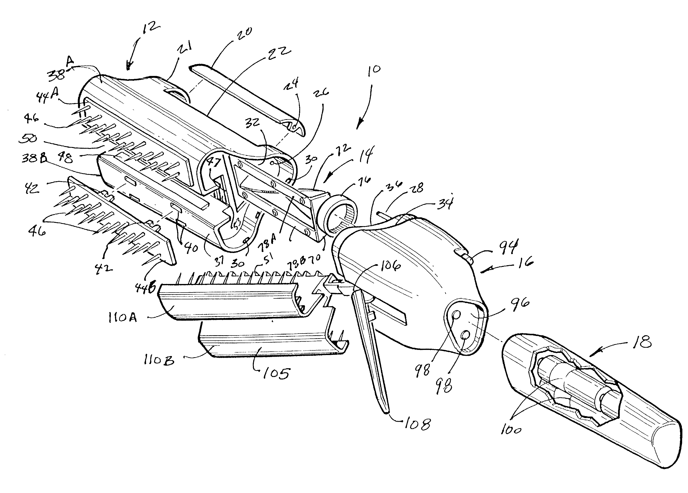
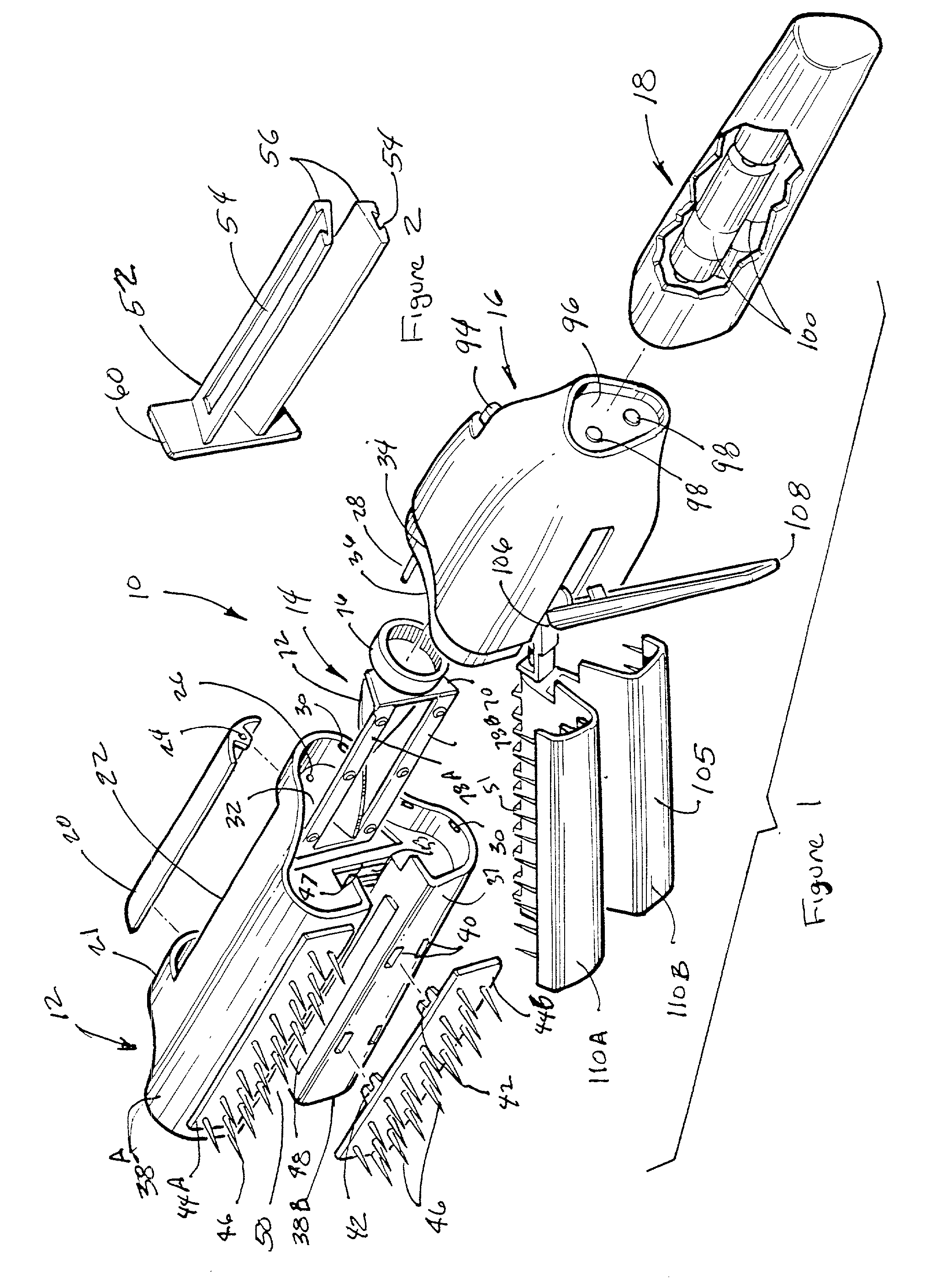
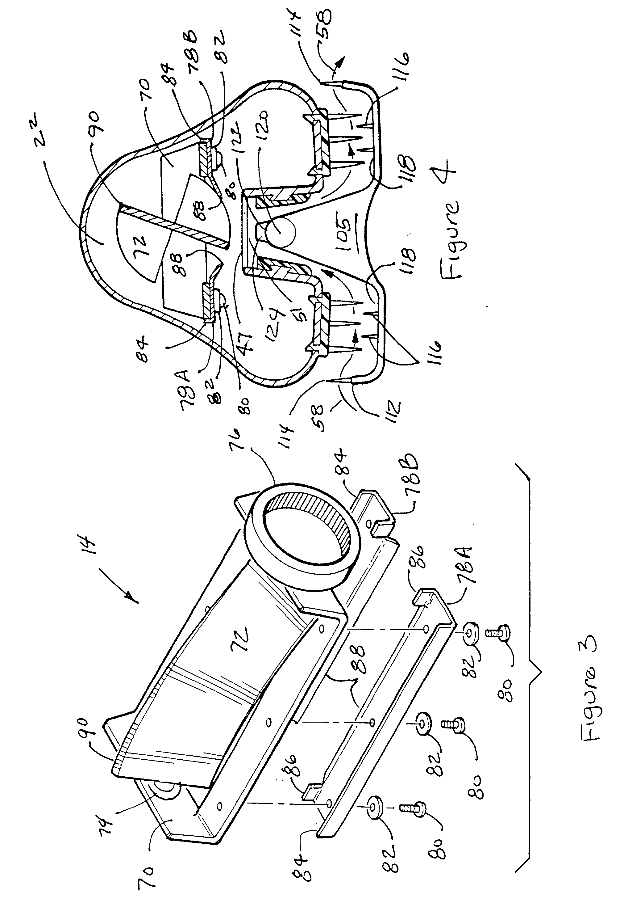
[0034] Referring now to the drawing FIG. 1 showing an exploded perspective view of the hair trimmer assembly 10. The cutter head assembly 12, the cutter blade assembly 14, the cutter body assembly 16 and the handle 18 are the major components of the hair trimmer assembly 10. The cutter head assembly 12 is shown with the transparent hair removal door 20 exploded away from the top lobe 21 of the internal containment area 22 that holds the cut ends of the hair shafts 23 drawn through the device and trimmed. The locking orifice 24,in the end matches the orifice 26 in the cutter head that is in alignment with the locking pin 28 located in the cutter body 16 so that when the cutter head assembly and the cutter body are assembled, the hair removal door 20 cannot be removed thereby providing a means to prevent access to the internal containment area 22 during operation of the device 10.

[0035] A plurality of raised ridges 30 around inside perimeter edge of the female end 32 of the cutter hea...


PUM


Abstract

A hand held hair trimming device which when pulled through the hair cuts only a determined portion of the ends of hair strands while leaving adjacent hairs uncut. The device will cut a predetermined length off only the distal ends of the hair shafts each time it has the hair drawn through its serpentine channel. Angled encounter of the distal ends with the cutting blade is prevented by ridges and apertures encouraging such contact only at subtantially straight angles. The device may be held in either hand allowing the hair pass through in either direction by merely changing the rotational direction of the motor by moving the thumb switch. The blade section of the device may be adjustable for changing the amount of the determined length to be cut from the hair shafts or may be removable and replaceable with one of a plurality of differently configured blade assemblies thereby allowing for easy adjustment of the trimmed amount.

Description

[0001] 1. Field of the Invention[0002] The present invention relates to an improved device for the trimming of the hair. More particularly it relates to a device which will trim a predetermined substantial equal amount from the ends of the individual hair shafts distal from the hair follicles for removal of the split ends derived from frequent combing and washings. The predetermined lengths of the hair shafts are thus trimmed while leaving adjacent longer hair shafts intact. The device also features removable blade mechanisms for user adjustment of hair trim length and optionally hair drying.[0003] 2. Prior Art[0004] Because of the changing styles and the inevitability that the hair on a person's head will grow and need to be cut, visits to hairstylists and barbers are a common occurrence in the United States and throughout the world. Hairstylists and barbers are trained in the art of cutting hair to their clients specifications using motorized and hand held implements such as sciss...

Claims


Application Information

Patent Timeline
IPC IPC(8): B26B19/22B26B19/20B26B19/38B26B19/44B26B19/48
CPCA45D24/36B26B19/16B26B19/22B26B19/48B26B19/382B26B19/44B26B19/3813
Inventor TALAVERA, VICTOR C.
Owner TALAVERA HAIR PROD INC
Learn More