
Interference signal canceling apparatus and interference signal canceling method

a technology of interference signal and apparatus, applied in the direction of amplitude demodulation, line-fault/interference reduction, baseband system details, etc., can solve the problems of affecting the ranking process, and affecting the accuracy of the ranking process

Inactive Publication Date: 2002-10-31
PANASONIC CORP
View PDF4 Cites 4 Cited by
  • Summary
  • Abstract
  • Description
  • Claims
  • Application Information

AI Technical Summary

Benefits of technology

[0012] It is therefore an object of the invention to provide an interference signal canceling apparatus and an interference signal canceling method, that is able to relieve the traffic in bus lines and suppress the amount of processing in a ranking process wherein the number of users is increased and the transmission rate is increased.

Problems solved by technology

Further, even if the spreading codes of the respective user signals are orthogonal to each other, interference occurs where the time correlation is not zero.
However, in the above-described prior art interference signal canceling apparatus, where the number of users is increased and the transmission rate is increased, there are problems in that the traffic in bus lines is made heavy or the amount of processing in a ranking process will be remarkably increased.

Method used


Image

  • Interference signal canceling apparatus and interference signal canceling method
  • Interference signal canceling apparatus and interference signal canceling method
  • Interference signal canceling apparatus and interference signal canceling method

Examples


first embodiment

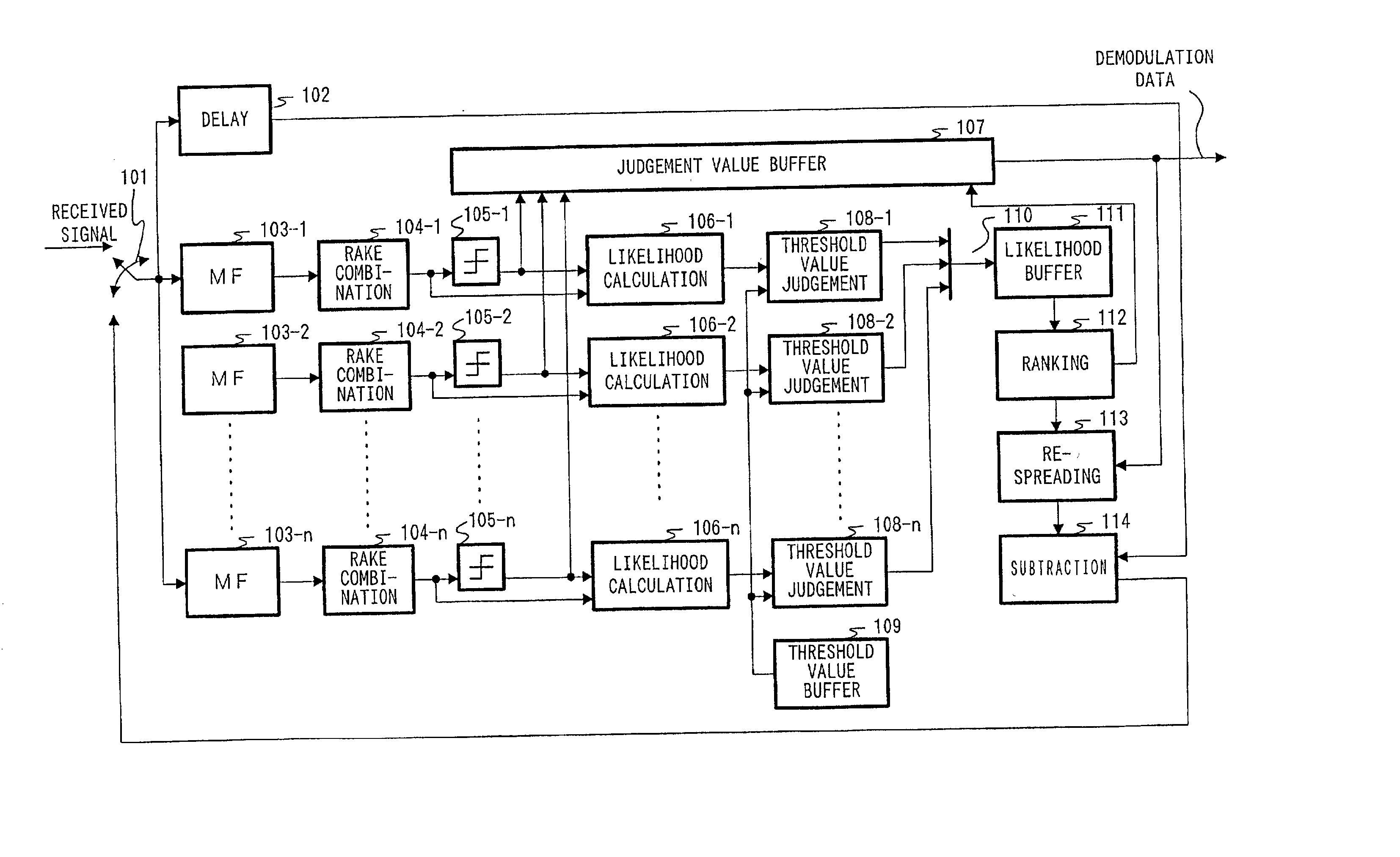
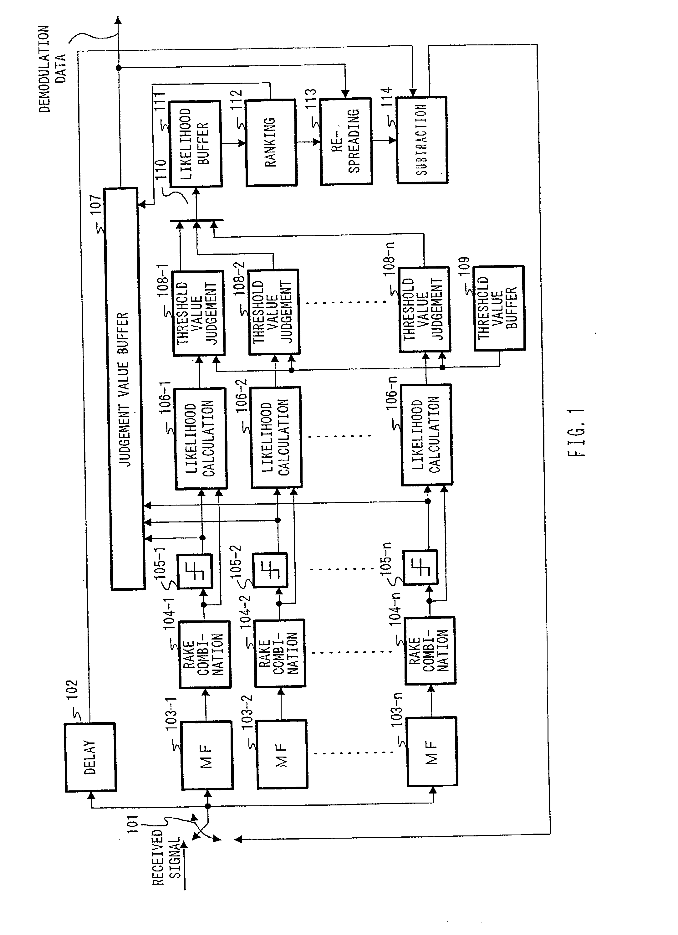
[0019] FIG. 1 is a block diagram showing a brief structure of an interference signal canceling apparatus according to the invention. In FIG. 1, received signals are signals that have been received through an antenna (not illustrated), and are those in which a plurality of user signals are combined in the same frequency band by the CDMA system.

[0020] Switch 101 selects either one of the received signals or signals that are outputted from a subtractor 114, and outputs the same to a delay unit 102 and matched filters 103-1 through 103-n.

[0021] The delay unit 102 delays signals, which are selected by the switch 101, by an appointed duration of time, and outputs the signals to the subtractor 114.

[0022] Respective matched filters 103-1 through 103-n take a correlation with spreading codes assigned user by user with respect to the input signals selected by the switch 101, suppress other user signals, which are signals other than signals for an appointed user, and thermal noise, and output ...

embodiment 2

[0048] A second embodiment is a mode for adequately controlling the threshold value that is used for judgement of a threshold value. Hereinafter, a description is given of an interference signal canceling apparatus according to the second embodiment, using a block diagram in FIG. 3. Also, in an interference signal canceling apparatus shown in FIG. 3, components that are common to those of the interference signal canceling apparatus shown in FIG. 1 are given the same reference numbers, and overlapping description thereof is omitted.

[0049] The interference signal canceling apparatus shown in FIG. 3 is such that a threshold value controlling unit 201 is added to the interference signal canceling apparatus shown in FIG. 1.

[0050] The threshold value controlling unit 201 controls a threshold value, which is stored in the threshold value buffer on the basis of the number of likelihoods exceeding the threshold value, by inputting signals showing the likelihood being the threshold value or m...

embodiment 3

[0056] However, where the first established threshold value is not adequate even in cases where the threshold value used for judgement of a threshold value is adequately altered as in the second embodiment, there remains such a problem in that it takes much time until the threshold value is controlled so as to become an adequate threshold value.

[0057] Herein, since there is no case where the line quality is radically changed between continuous slots, it is considered that a threshold value suitable for an interference signal canceling process in new slots is not greatly different from the threshold value used in the last slot.


PUM


Abstract

Respective threshold value judging units 108-1 through 108-n compare the likelihoods calculated by the corresponding likelihood calculators 106-1 through 106-n with threshold values stored in a threshold value buffer 109 in terms of size, and output signals, which show the corresponding likelihood in only a case where the likelihood is the threshold value or more, through a likelihood transmission bus 110. The rank decision unit 112 ranks the symbols for which the likelihood is an appointed threshold value or more, on the basis of the likelihoods stored in the likelihood buffer 111, whereby it is possible to relieve the traffic of a bus line and to suppress the amount of processing in a ranking process with respect to all non-demodulated symbols.

Description

DESCRIPTION[0001] 1. Technical Field[0002] The present invention relates to an interference signal canceling apparatus and an interference signal canceling method, which are incorporated in a base station, etc., of the CDMA mobile communication system.[0003] 2. Background Art[0004] Recently, in a mobile communication system whose demand has been remarkably increasing, it is an important factor to attempt an increase in the capacity of communication channels. And, the CDMA system has been noted as a multiple division system that can increase the capacity of the channels.[0005] Herein, a plurality of user signals are transmitted in the same frequency band in the CDMA system, where it is possible to completely separate signals of respective users from other user signals unless spreading codes of the respective user signals are orthogonal to each other. Further, even if the spreading codes of the respective user signals are orthogonal to each other, interference occurs where the time co...

Claims


Application Information

Patent Timeline
Patent Type & Authority Applications(United States)
IPC IPC(8): H04J13/00H04B1/10H04B1/7107H04B1/7115H04B7/26H04L7/08H04W88/08
CPCH04B1/71057H04B2001/71077H04B1/71075
Inventor AOYAMA, TAKAHISAMIYA, KAZUYUKIMIYOSHI, KENICHI
Owner PANASONIC CORP
Learn More