Current amplifier structure

Inactive Publication Date: 2002-11-14
SHENZHEN STS MICROELECTRONICS
View PDF2 Cites 7 Cited by
  • Summary
  • Abstract
  • Description
  • Claims
  • Application Information

AI Technical Summary

Benefits of technology

[0016] It is yet another object of the invention that the current amplifier circuit structure be easily adaptable to a variety of applications, such as those applications requiring current amplification with precisely controllable gain characteristics and those applications calling for voltage-to-current conversion.
[0017] Therefore, according to the structure of the present invention, a simple integrated circuit is used to amplify the input signal. The integrated circuit consists of an amplifier cell, which may be used as a building block in many circuit configurations, including a variable gain current amplifier, and a AC or DC voltage-to-current converter. The basic amplifier cell consists of several functional elements, including an input stage, a current mirror stage, and an output stage. The input stage and current mirror stage allow the input signal to be duplicated while isolating the input signal. This duplicated signal is used as input to the output stage. The output stage uses a current mirror to produce two identical output currents, one suitable for feedback or other purposes, at corresponding output terminals. These output currents may then be used to produce current amplification or voltage-to-current conversion through the judicious use of one or more resistive elements coupled to these output terminals.
[0019] AC or DC voltage-to-current conversion may also be performed using the simple current amplification cell by using a voltage differential pair as input to the cell. The output current is determined using a resistive element. In an exemplary embodiment of the present invention, voltage-to-current conversion is enabled by presenting a voltage signal between the two terminals of the input stage. This input voltage signal produces an identical voltage at the input to the output stage through the action of the current mirror. Through the action of the current mirror in the output stage, the identical output currents are present at the two output terminals. By placing a resistive element at the node between the first output terminal and ground, the output current from the second terminal is found to be proportional to the input voltage. The resistive element determines the value of the output current.

Problems solved by technology

While there are many standard circuits available for voltage amplification, current amplification circuits are uncommon.
A further drawback of this circuit is that the values of gain that may be produced are limited to the relative values of the resistors and the emitter areas.

Method used


Image

  • Current amplifier structure
  • Current amplifier structure
  • Current amplifier structure

Examples


Embodiment Construction

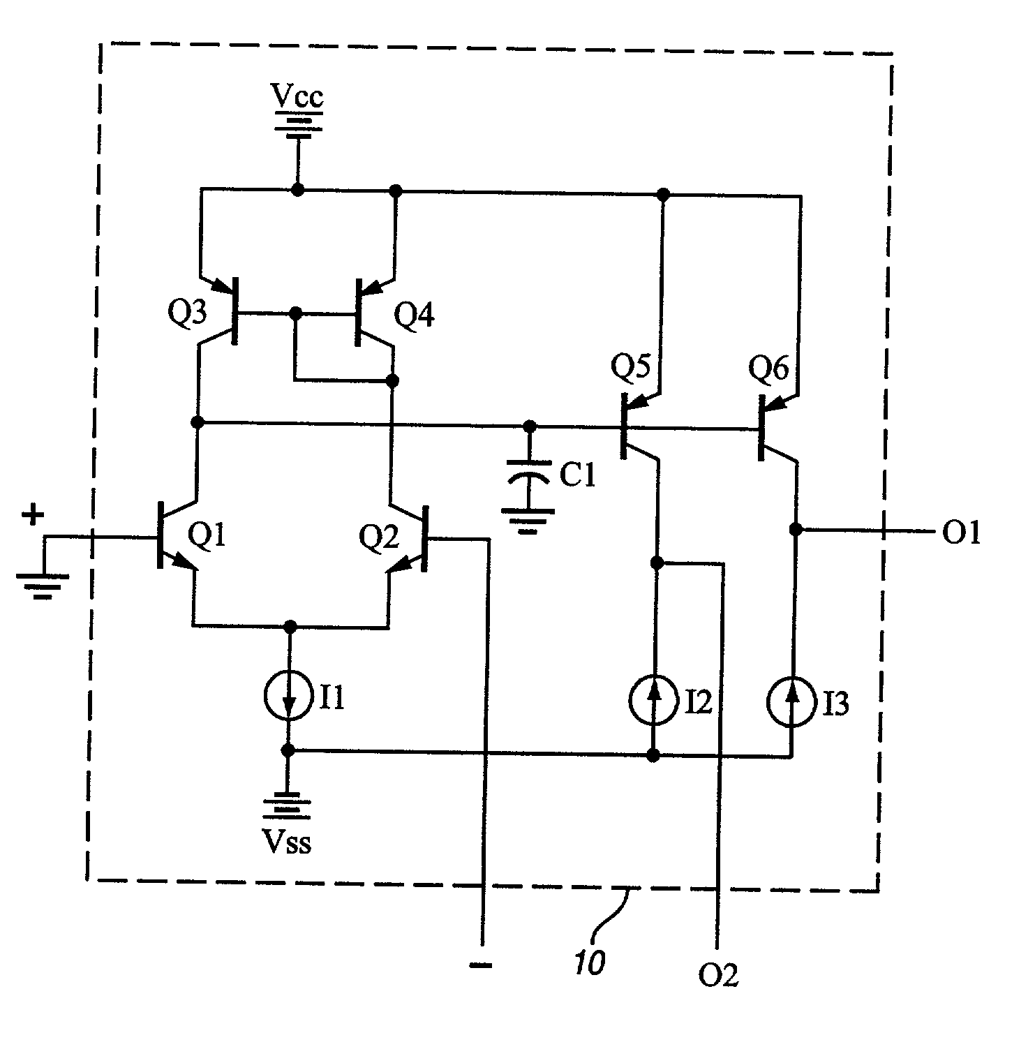
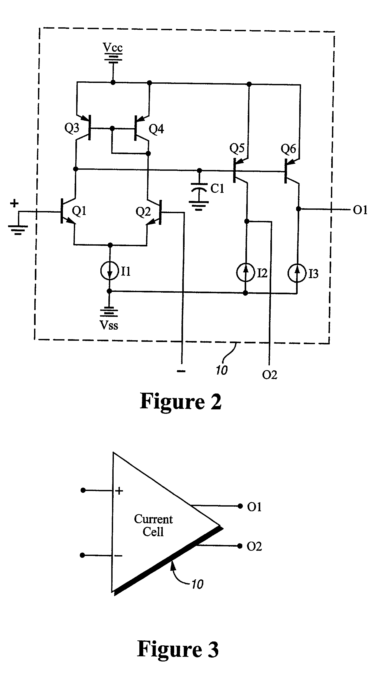
[0030] The current amplification cell of the present invention produces identical output currents when a one-terminal or two-terminal input signal is applied thereto. Referring now to FIG. 2, the current amplifier cell 10 for creating identical output currents in accordance with the present invention is shown. Current amplifier cell 10 contains the following elements: n-p-n / p-n-p transistors Q1, Q2, Q3, Q4, Q5, and Q6, capacitive element C1, and current sources I1, I2, and I3. A constant current I1 is coupled to both emitters of transistors Q1 and Q2. The other terminal of current I1 is coupled to a constant supply voltage Vss. Transistors Q1 and Q2 are coupled as a differential pair input stage as shown. The base of transistor Q1 is coupled to the positive input terminal, while the base of transistor Q2 is coupled to the negative input terminal. The collector of Q1 is coupled to the collector of Q3 in the Q3-Q4 current mirror. The collector of Q2 is coupled to the collected to the ...


PUM


Abstract

A circuit structure for performing current amplification. The circuit structure may be standardized as a current amplifier cell such that many types of applications requiring current amplification may be created. The basic amplifier cell, which may accept voltage or current sources as an input signal, produces two identical output signals which may be used for feedback or serve as input to additional amplifier stages. This simple structure may be extended to perform current amplification with variable gain or AC or DC voltage-to-current conversion through the use of appropriately selected resistive elements.

Description

PRIORITY[0001] Foreign Priority under Title 35, U.S. Code, Section 119, is claimed to Chinese Application 01104518.3, filed Feb. 10, 2001, within 12 months prior to the filing date of the instant application[0002] 1. Technical Field[0003] The present invention relates generally to analog integrated circuits and more specifically to current amplification including voltage-to-current conversion and current amplification.[0004] 2. Discussion of the Prior Art[0005] While there are many standard circuits available for voltage amplification, current amplification circuits are uncommon. In a typical current amplifier, amplification is achieved through the use of a current mirror with different emitter areas for each transistor and different emitter resistors. At large values of gain, precise matching of emitter areas and resistance becomes critical.[0006] Referring to FIG. 1, the classical manner of amplifying the current is shown. The current amplifier of FIG. 1 includes current source I1...

Claims


Application Information

Patent Timeline
IPC IPC(8): H03F1/34H03F3/45
CPCH03F1/34H03F2203/45511H03F3/45475H03F3/45085
Inventor ZHA, GANGNG, SOLOMON
Owner SHENZHEN STS MICROELECTRONICS
Why Eureka
Try Eureka