Golf club head having a device for resisting expansion between opposing walls during ball impact

a golf club head and wall technology, applied in the field of golf club head, can solve the problems of large amount of expertise, less durable wood golf club head, and variable density and hardness

Inactive Publication Date: 2002-11-14
GOLFSMITH LICENSING
View PDF0 Cites 49 Cited by
  • Summary
  • Abstract
  • Description
  • Claims
  • Application Information

AI Technical Summary

Benefits of technology

0026] It is therefore a principal object of the present invention to provide a metal wood golf club head having a te

Problems solved by technology

Generally wooden golf club heads are less durable, vary in density and hardness and require great expertise through the manufacturing process.
As driver club heads become larger, their ability to prevent deformation at impact with the golf ball becomes more difficult.
Even with the use of high performance materials such as titanium or carbon fiber, the weight constraints common in most driver club heads make it imperative to design driver club heads using thin walls.
The resulting redirection of energy transfer causes the dr

Method used


Image

  • Golf club head having a device for resisting expansion between opposing walls during ball impact
  • Golf club head having a device for resisting expansion between opposing walls during ball impact
  • Golf club head having a device for resisting expansion between opposing walls during ball impact

Examples


Embodiment Construction

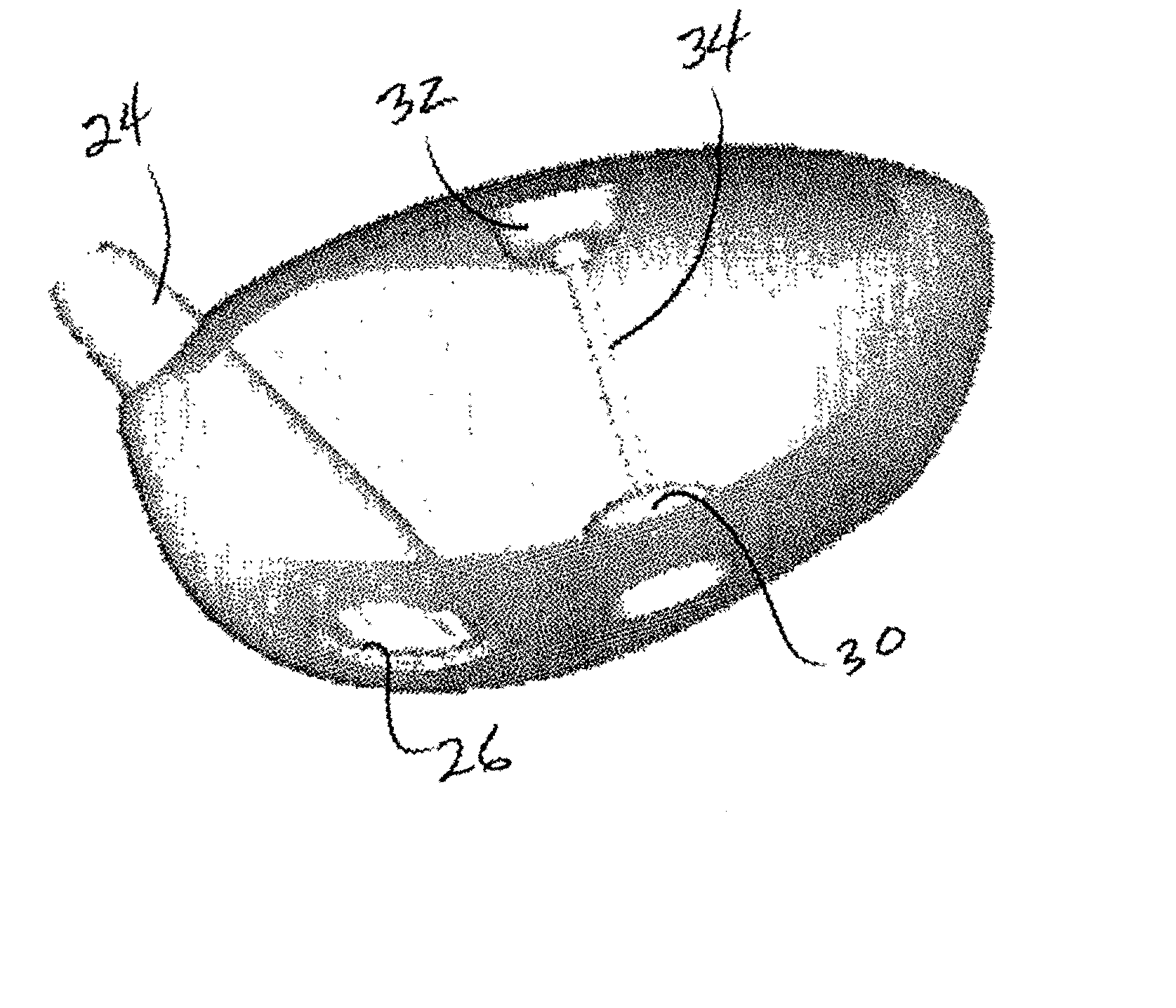
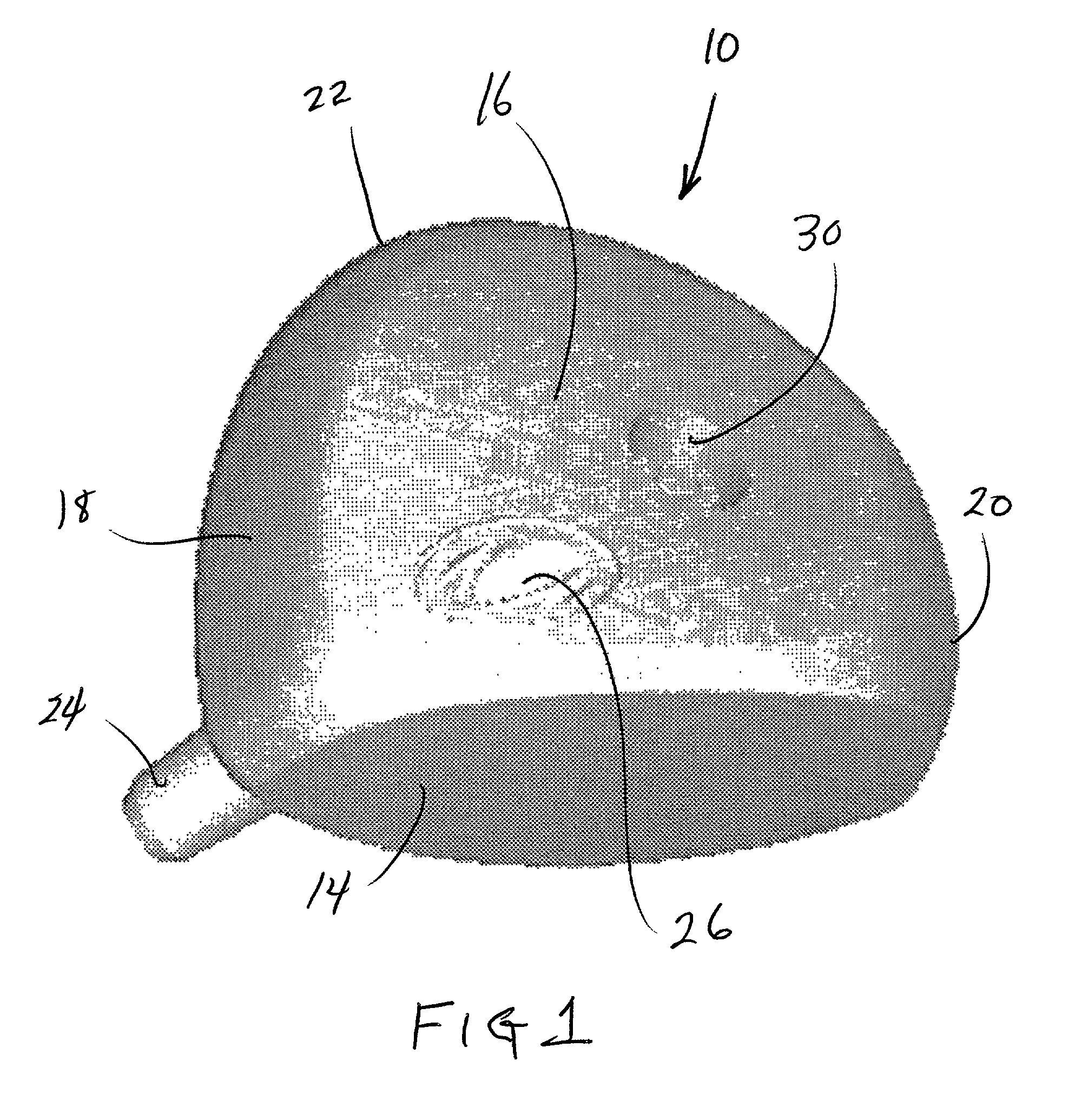
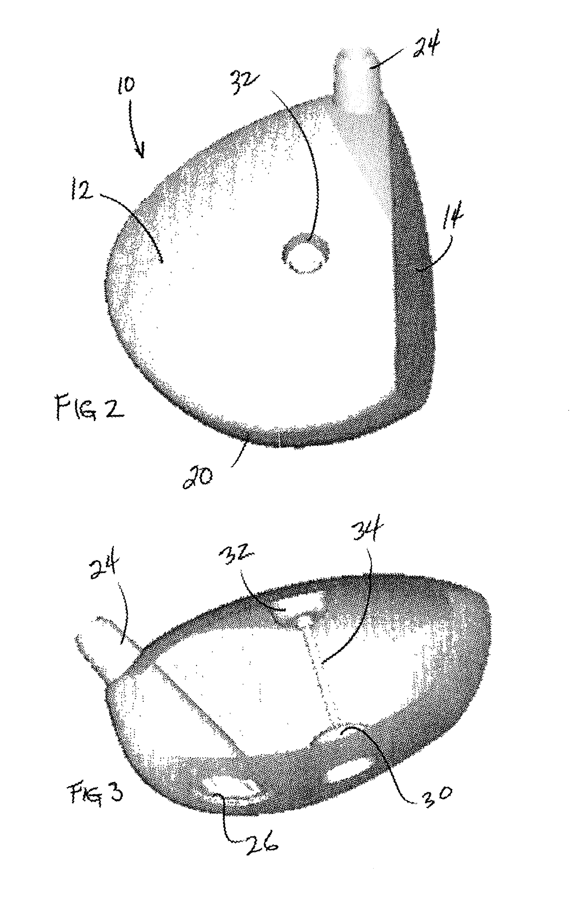
[0040] Referring to the accompanying drawings, it will be seen that a preferred embodiment of a golf cub metal wood head 10 comprises a top or crown 12, a face or hitting surface 14, a bottom or sole 16, a heel 18, a toe 20, a back 22 and a hosel 24. These various surfaces are generally configured as in typical driver heads forming a conventionally shaped golf club head. Hosel 24 extends into the interior of the head 10 and to the sole 16 forming a hosel / sole aperture 26 as seen in FIGS. 1 and 4.

[0041] Unlike conventional driver heads, the head 10 of the illustrated embodiment provides a sole recess 30 and a crown recess 32 at opposing locations on sole 16 and crown 12, respectively. Moreover, the present invention provides a tensioning device 34 which extends internally of head 10 between the sole recess 30 and the crown recess 32. Tensioning device 34 may be any high strength, lightweight, elongated member (i.e., wire) that can withstand tension forces exceeding at least several h...


PUM


Abstract

An improved golf driver club head wherein each driver club head has a tensioning device which places the peripheral/outer structure of the club head in compression thereby resulting in a stronger more rigid club head structure. This is accomplished by affixing the tensioning device to the crown (top) surface of the club head and to the sole (bottom) surface of the metal head. The device is affixed to the two surfaces of the club head and is pre-tensioned. The tensioning may be accomplished by compressing the two club head surfaces together then affixing the device to the opposed surfaces so that the surfaces are held in state of relative compression. Another way this can be accomplished is to affix the device to the two club head surfaces either through a hole or boss and to adjust the device by threading, gluing or other form of fastening. In the preferred embodiment the tensioning device comprises an elongated cylindrical member having respective end members. The top and bottom surfaces of the golf club head are each provided with a cylindrical depression or recess and an aperture or passage at the lower end of the depression. The passages are just large enough to accommodate the tensioning device, but are too small to pass the respective end members. During club head manufacture, the length of the device is selected to apply a compressive force between the head surfaces. Fine adjustment is accommodated by a threaded end member. The actual compression force may be selected to yield the best performance depending on the geometry, structure and material of the club head.

Description

[0001] 1. Field of the Invention[0002] The present invention relates generally to the field of golf club heads and more specifically to a golf club wood-type head having a tensioning device for better energy transfer.[0003] 2. Background Art[0004] Golf club wood heads that are made from metal (metal woods) and other more exotic high technology materials have distinct advantages over wooden club heads. Generally wooden golf club heads are less durable, vary in density and hardness and require great expertise through the manufacturing process. Metal and exotic materials woods on the other hand can be replicated consistently from the original design, use strong durable materials and are produced using proven manufacturing processes.[0005] Metal and exotic material woods out-perform wooden clubs because they use harder, stronger materials. The use of these materials enables the weight to be transferred to the club head perimeter thereby stabilizing the club head as it comes into impact ...

Claims


Application Information

Patent Timeline
IPC IPC(8): A63B53/04A63B53/06
CPCA63B53/0466A63B59/0088A63B2053/0437A63B2053/045A63B2053/0433A63B60/50A63B53/045A63B53/0437A63B53/0433A63B53/04
Inventor BOONE, DAVID D.
Owner GOLFSMITH LICENSING
Why Eureka
Try Eureka