Odd -number factor frequency divider and 90o phase splitter which operates from output signal of the frequency divider
a frequency divider and 90o phase splitter technology, applied in the direction of pulse technique, continuous circulation pulse counter, counting chain synchronous pulse counter, etc., can solve the problem of inability to obtain a pair of output signals, power consumption of the apparatus will be excessively increased, and it is not possible to use such an output signal directly in the factor 2 frequency divider type of phase splitter circui
- Summary
- Abstract
- Description
- Claims
- Application Information
AI Technical Summary
Benefits of technology
Problems solved by technology
Method used
Image
Examples
first embodiment
[0036] First Embodiment
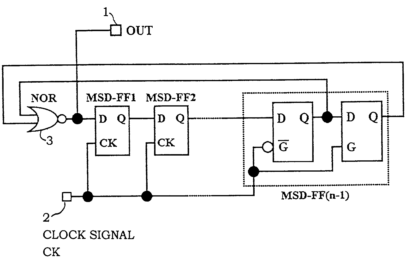
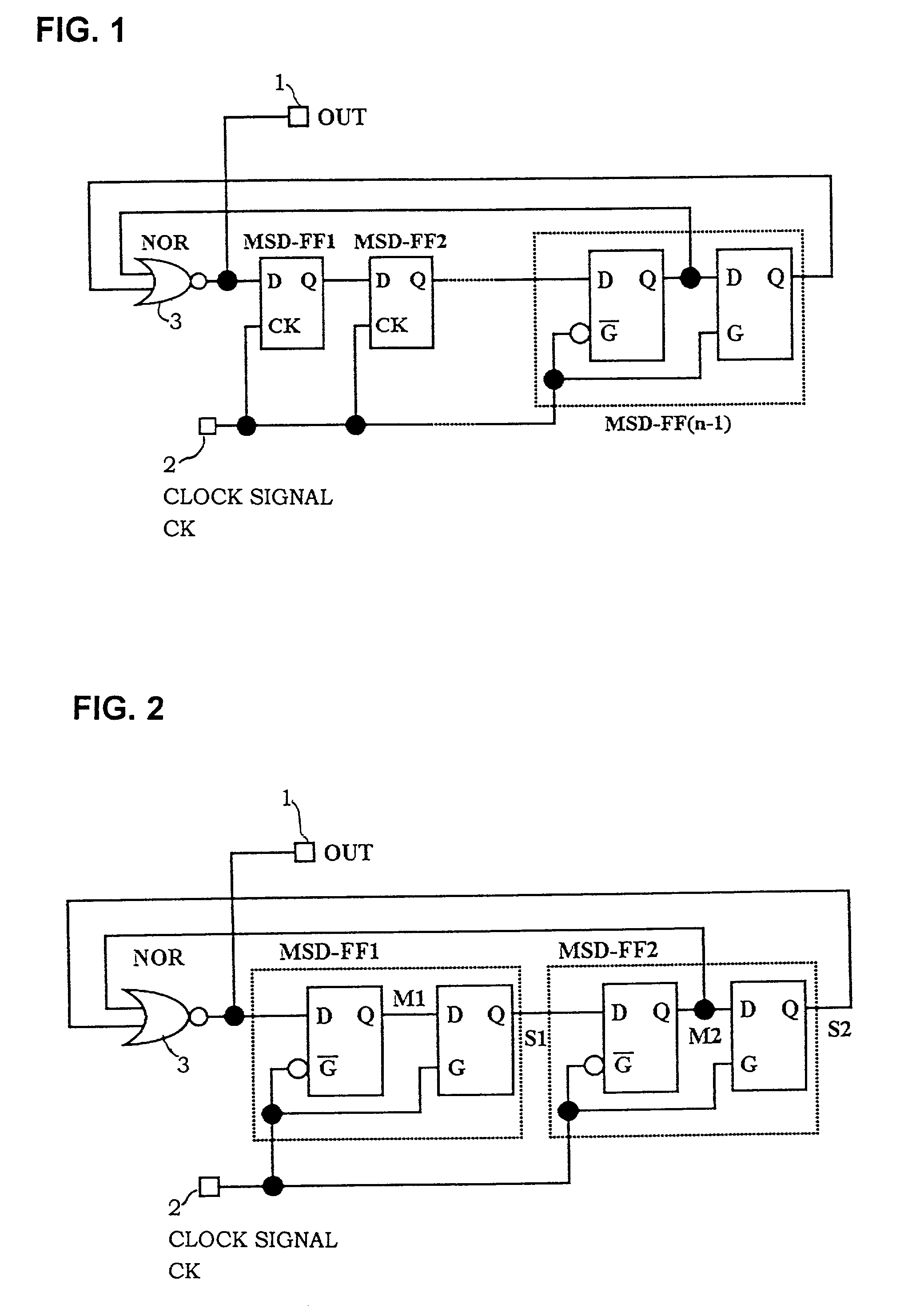
[0037] The first embodiment is an odd number factor frequency divider whereby an output signal is generated expressing the NOR function (i.e., negated logic sum) of respective Q-terminal output signals of a master D-type latch and slave D-type latch of a final stage MSD-FF of a series of cascade-connected MSD-FFs, with that output signal being applied to the D input terminal of a first-stage MSD-FF, while also constituting the final output signal from the frequency divider.
[0038] FIG. 1 is a block diagram showing the circuit configuration of this first embodiment, which is a factor (2n+1) frequency divider. In FIG. 1, MSD-FF1 and MSD-FF(n-1) are respectively the first stage and final stage of a cascade-connected plurality of MSD-FFs. The circuit performs frequency division of a clock signal CK which is supplied from an external source to an input terminal 2, to obtain a final output signal OUT on an output terminal 1. Numeral 3 denotes a NOR gate. Two basic fe...
second embodiment
[0046] Second Embodiment
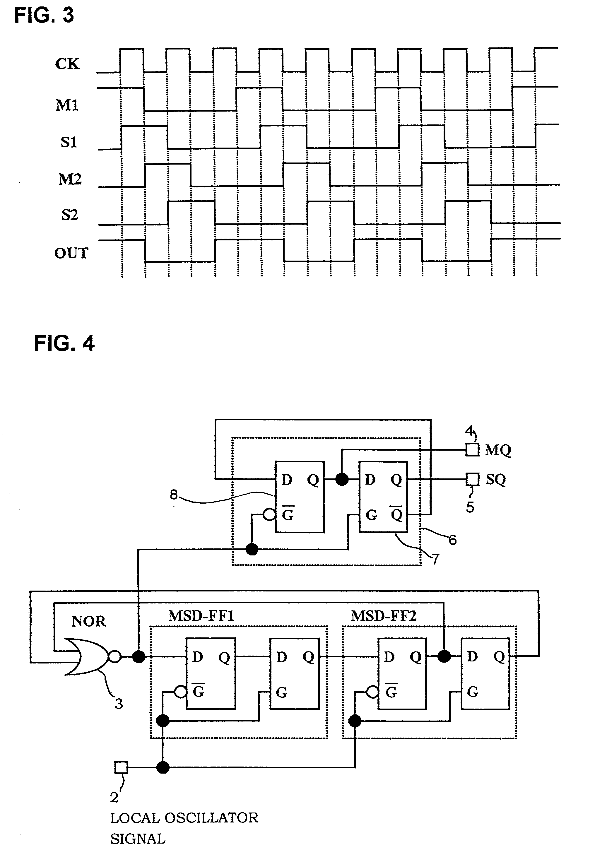
[0047] With a second embodiment of the invention, the output signal from the odd number factor frequency divider is applied as a clock signal to a 90.degree. phase splitter circuit which is implemented as a single MSD-FF, with the inverted Q output from the slave D-type latch applied to the D input terminal of the master D-type latch, as described above referring to FIG. 10A. The respective Q-terminal output signals from a master D-type latch and a slave D-type latch of that MSD-FF constitute the two final output signals from the phase splitter circuit.
[0048] FIG. 4 shows the configuration of the second embodiment, which is assumed for simplicity of description to use a factor 3 frequency divider in accordance with the first embodiment of the invention. It is assumed that the circuit is for use in a radio apparatus such as a mobile radio apparatus, and that the clock signal which is supplied to the factor 3 frequency divider is a local oscillator signal, i.e....
PUM
 Abstract
Description
Claims
Application Information
 - R&D
- Intellectual Property
- Life Sciences
- Materials
- Tech Scout
- Unparalleled Data Quality
- Higher Quality Content
- 60% Fewer Hallucinations
Browse by: Latest US Patents, China's latest patents, Technical Efficacy Thesaurus, Application Domain, Technology Topic, Popular Technical Reports.
© 2025 PatSnap. All rights reserved.Legal|Privacy policy|Modern Slavery Act Transparency Statement|Sitemap|About US| Contact US: help@patsnap.com


