Vehicle with compliant drive train

a technology of drive train and vehicle, applied in the direction of vehicles, transportation and packaging, etc., can solve the problems of inability to roll over obstructions, inability to adapt to use on varying terrains, absurd radius of wheels, etc., and achieve the effect of simple design, reduced vehicle weight, and high mobility

Inactive Publication Date: 2002-12-05
BIOROBOTS
View PDF22 Cites 29 Cited by
  • Summary
  • Abstract
  • Description
  • Claims
  • Application Information

AI Technical Summary

Benefits of technology

0017] The primary object of our invention is to enable a vehicle with few actuators to move quickly and climb obstacles. The advantages are that such a vehicle is highly mobile, has a relatively low-cost, is lightweight, and uses a simple design.
0018] An object of our invention is to enable the primary object for a vehicle with one drive motor used for propulsion. Because gear-motors are one of the most massive components on an electrically-actuated legged vehicle, reducing their number reduces the vehicle's weight and increases its payload capacity. Furthermore, when a single leg has a solid foothold and the other legs are slipping, the single leg requires a great amount of torque to propel the vehicle. In a one drive-motor design, all of the motor's torque is available for that leg. When individual legs or joints are driven by individual motors, each motor must be powerful enough for the worst case scenario. This requirement results in many large, heavy motors. The motor for a single drive-motor vehicle design can weigh much less than the combined weight of all of the motors on a vehicle with legs or joints driven by individual motors. A one-motor design also eliminates the need for individual active control of joints, which simplifies the controller. This simplification could reduce the possible behaviors that the robot can perform, but our invention solves these potential problems.
0019] An object of our invention is for driving appendages or legs to move the vehicle forward or backward with a nearly constant speed given constant speed of the one drive motor. The advantage is that the drive-motor does not have to accelerate and decelerate during each cycle of leg motion to move the vehicle at near constant speed. For a robot with individually actuated legs (US PA 2001/0054518) to move at a constant speed, it must swing its legs more rapidly

Problems solved by technology

A significant limitation of such designs, however, is that they are not easily adaptable for use on varying terrains, with some modification to the vehicle or its appendages typically required to even transition between climbing obstacles and moving on a level surface.
A further limitation of a standard wheel is its inability to roll over obstructions that are more than some portion of its radius.
As larger and larger obstacles must be surmounted, the radius of the wheels required becomes absurd.
With no provision for dynamically or passively modifying the phase relationship of the legged-wheels, however, this device was not able to adjust its gait, limiting is climbing ability as well as its speed on level surfaces.
Also, having only two driving appendages, its control and stability were limited.
Each leg on one of these vehicles is typically a complicated mechanism it its own right, with multiple degrees of freedom or joints.
In place of, or in addition to, multiple actuators per leg, some designs require complicated linkages, clutches, and transmissions to drive the legs.
While decoupling these motions reduces power consumption on level groun

Method used


Image

  • Vehicle with compliant drive train
  • Vehicle with compliant drive train
  • Vehicle with compliant drive train

Examples


Embodiment Construction

: DESIGN

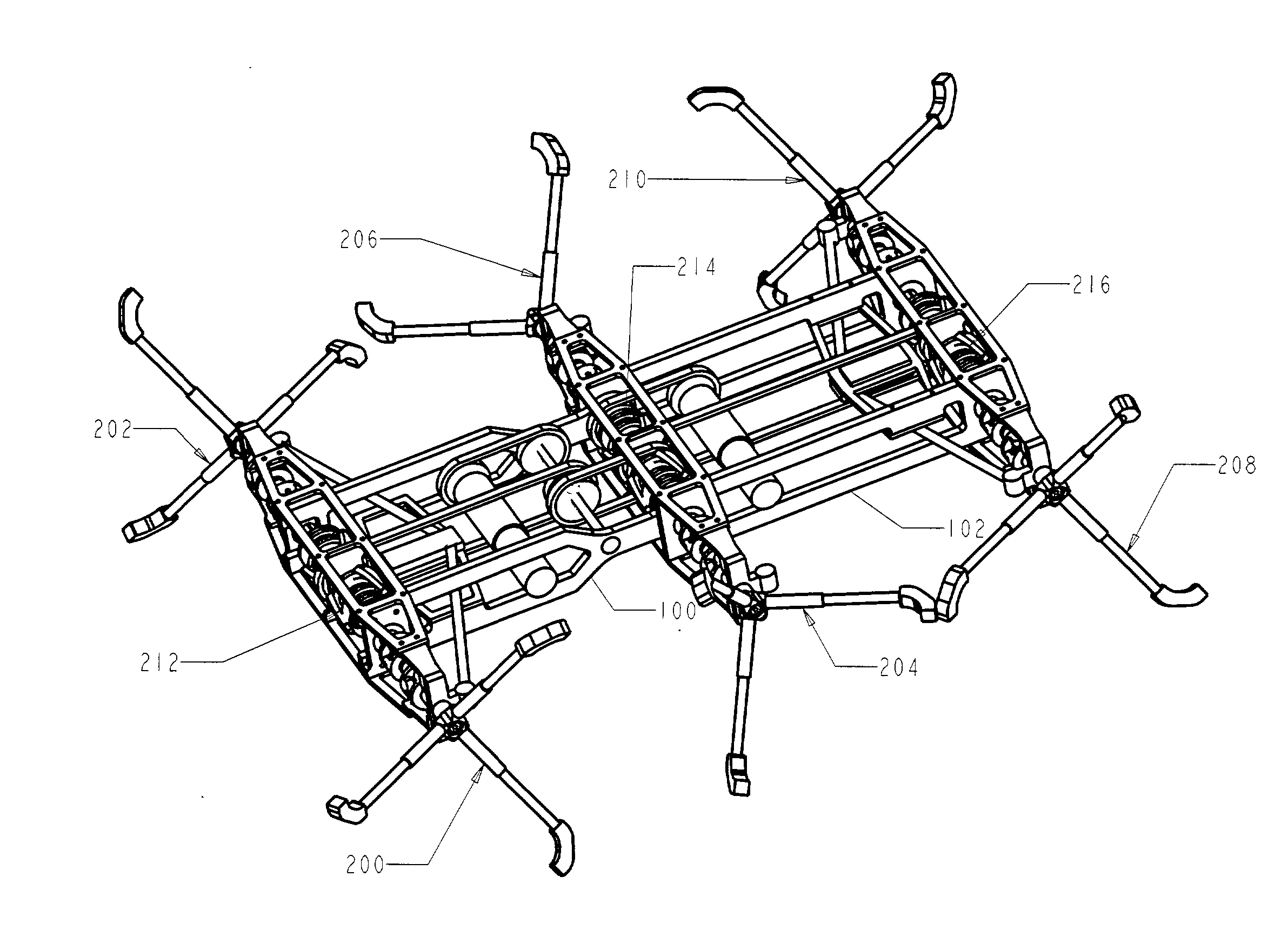
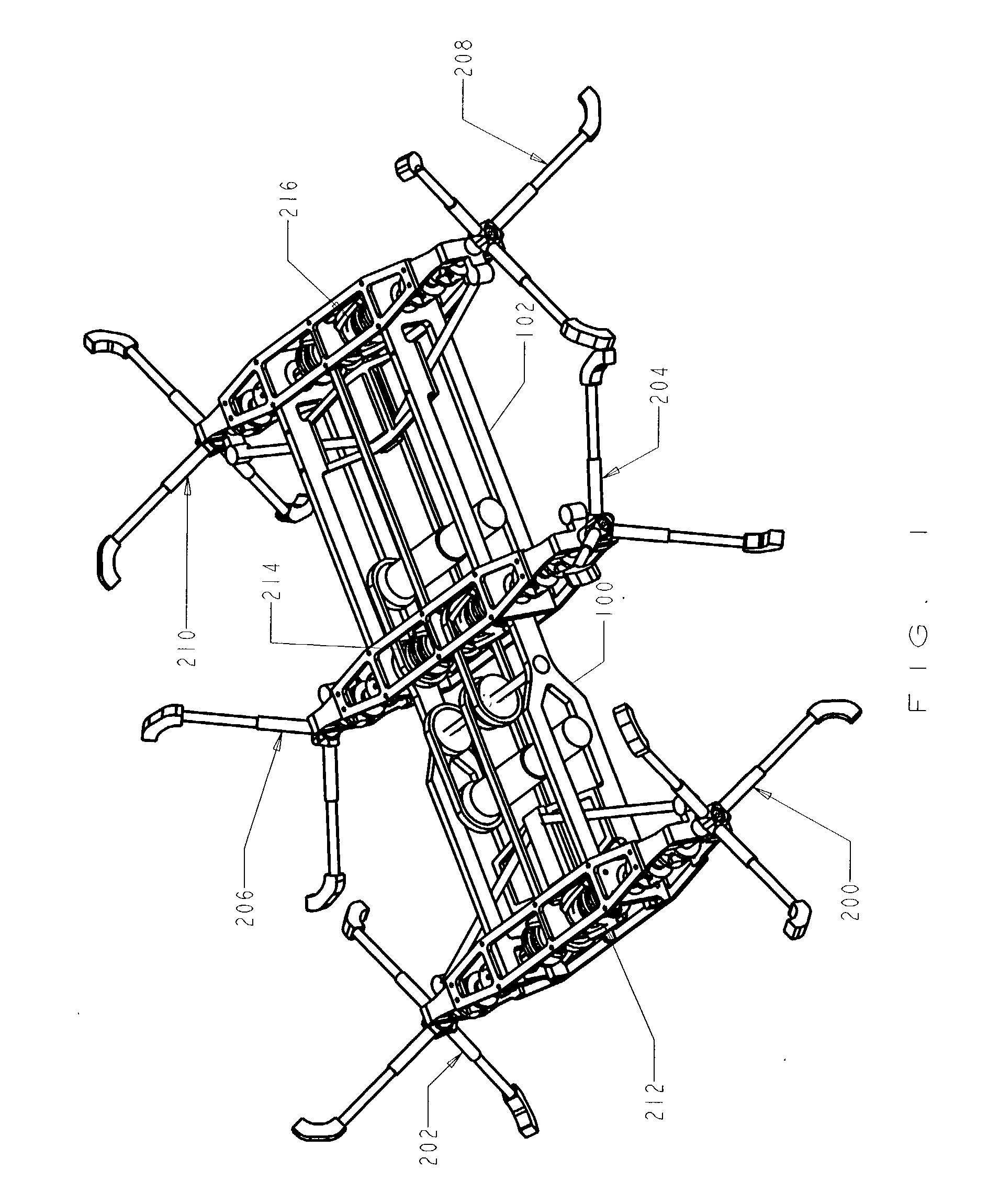
[0158] A vehicle that embodies the invention is shown in FIG. 1.
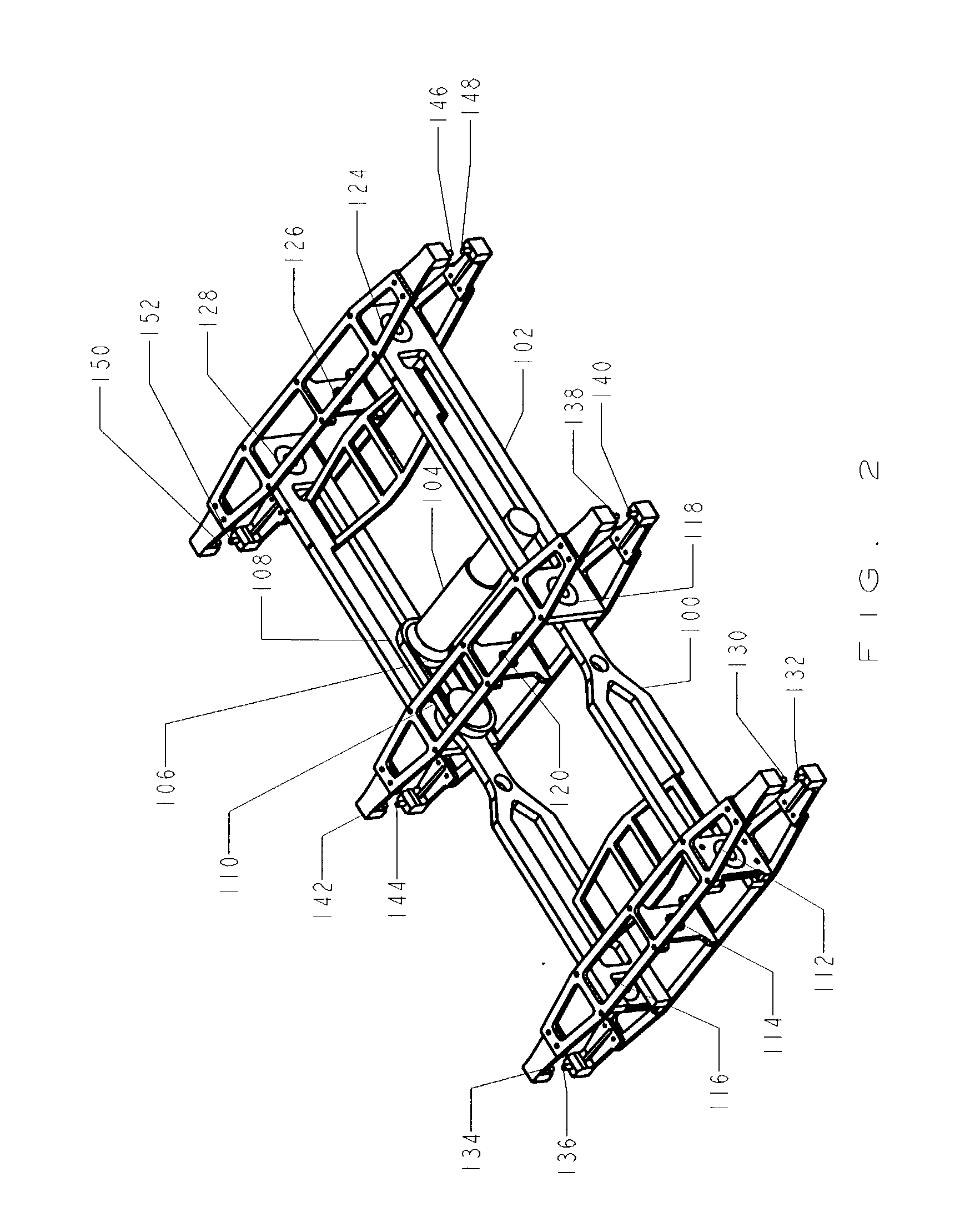
[0159] Body: FIG. 2

[0160] The body of the vehicle, shown in FIG. 2, consists of a rigid front segment 100 and a rigid rear segment 102 that are articulated about an axis that coincides with the centerline of the middle axle 214 of the vehicle. A body-joint motor 104 with integral transmission, mounted on the rear segment of the body, rotates the body joint. A drive sprocket 106 is mounted on the output shaft of the transmission. A chain 108 connects the drive sprocket to a driven sprocket 110, which is attached to the front segment of the body. The centerline of the driven sprocket corresponds to the centerline of the middle axle. The motor rotates the front segment up or down relative to the rear segment.

[0161] Drive Train: FIG. 3A and 3B

[0162] A drive-motor 218 with integral transmission drives front 212, middle 214 and rear 216 axle assemblies through the drive train shown in FIGS. 3A and 3B. The front axle a...


PUM


Abstract

A vehicle that is propelled by as few as one actuator through a compliant drive train can move quickly on relatively smooth terrain and can climb obstacles. The body of the vehicle may consist of a single segment or multiple segments connected by articulating joints. The driving appendages can take different forms including legs or specialized legs with multiple spokes attached to a rotating hub. The driving appendages can be propelled by as few as one actuator. The driving appendages are each serially connected to their actuator(s) by a compliant device. The compliant devices permit relative motion between driving appendages that share the same actuator. A springably biased compliant device maintains nominal-desired phasing among driving appendages until one of them is forcibly perturbed. The phasing of the driving appendages, or gait, adapts to the terrain. Mechanical stops limit the excursion of the compliant device such that a new desirable leg phasing is reached for climbing large obstacles. The elasticity of the compliant device restores the phasing of the driving appendages to their nominal state when the perturbation is removed. Compliance in the driving appendages and feet smooth the cyclic motion of the body. Compliant feet conform to the terrain and provide improved traction. Steering mechanisms rotate the plane of action of the driving appendages.

Description

[0001] This application is entitled to the benefit of Provisional Patent Application Ser. No. 60 / 295,778 filed Jun. 4, 2001. "An Insect-Inspired Unmanned Ground Vehicle with Improved Mobility," Roger D. Quinn et al.REFERENCE TO SEQUENCE LISTING, A TABLE, OR A COMPUTER PROGRAM LISTING COMPACT DISK APPENDIX[0003] Not applicable[0004] 1. Field[0005] Generally, this invention relates to mobile vehicles and more specifically to legged vehicles. This invention also may be used to improve the mobility of vehicles that use wheels, tracks and other driving appendages.[0006] Classifications:[0007] 180 / 8.1 Motor Vehicles / Stepper[0008] 180 / 8.6 Motor Vehicles / Stepper with Alternatively Lifted Feet or Skid[0009] 2. Prior Art[0010] Many tasks require a vehicle or mobile robot capable of traversing a variety of terrains, including broken ground, gravel, and stairways. In many of these environments, a standard wheel is a hindrance. Early prior art in this field dealt primarily with agrarian needs, s...

Claims


Application Information

Patent Timeline
IPC IPC(8): B62D57/02
CPCB62D57/022
Inventor QUINN, ROGER D.KINGSLEY, DANIEL A.OFFI, JOHN T.RITZMANN, ROY E.
Owner BIOROBOTS
Why Eureka
Try Eureka