Multi-wavelength optical modulation circuit and wavelength-division multiplexed optical signal transmitter

a multi-wavelength optical modulation circuit and wavelength-division multiplexing technology, applied in multiplex communication, instruments, optical elements, etc., can solve the problems of increasing the cross-talk effect between the high-power wavelengths and the low-power wavelengths, and the power level deviation between each of the wavelength channels is generated

Active Publication Date: 2002-12-19
NIPPON TELEGRAPH & TELEPHONE CORP
View PDF8 Cites 54 Cited by
  • Summary
  • Abstract
  • Description
  • Claims
  • Application Information

AI Technical Summary

Problems solved by technology

Namely, in this type of AWG for channel demultiplexing it is not possible to demultiplex multi-wavelength light having a frequency band equal to or wider than the FSR into individual wavelength channels.
When repetitive short optical pulses are used, as is shown in FIG. 32, the problem arises that a power level deviation is generated between each of the wavelength channels obtained by the spectrum slicing.
If the power is not uniform for each wavelength, the cross-talk effect generated by the high powered wavelengths to the low powered wavelengths increases and excessive degradation may occur.
Moreover, if the total power is decreased so that high powered wavelengths do not cause degradation due to the nonlinear effect, noise in the low powered wavelengths increases.

Method used


Image

  • Multi-wavelength optical modulation circuit and wavelength-division multiplexed optical signal transmitter
  • Multi-wavelength optical modulation circuit and wavelength-division multiplexed optical signal transmitter
  • Multi-wavelength optical modulation circuit and wavelength-division multiplexed optical signal transmitter

Examples


first embodiment

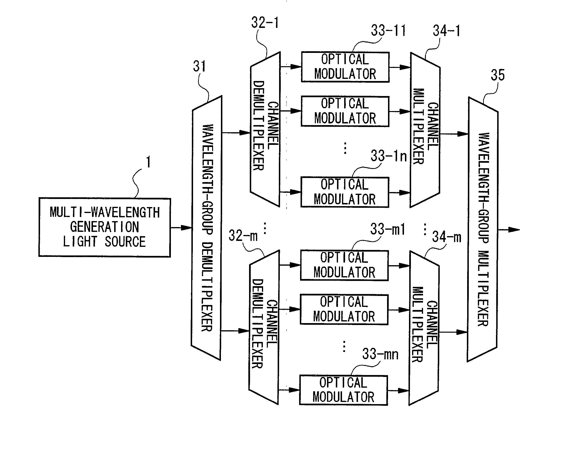
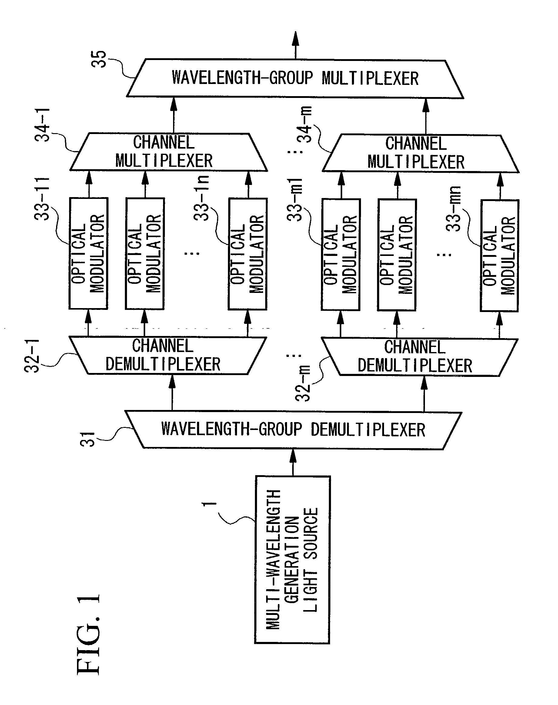
[0044] FIG. 1 shows the wavelength-division multiplexed optical signal transmitter according to the present invention.

[0045] In FIG. 1 the wavelength-division multiplexed optical signal transmitter of the present embodiment is provided with a multi-wavelength generation light source 1 that generates multi-wavelength light having a plurality of wavelengths, a wavelength-group demultiplexer 31 that demultiplexes the multi-wavelength light into respective wavelength groups formed by a respective plurality of wavelength channels, channel demultiplexers 32-1 to 32-m that demultiplex each wavelength group respectively into the plurality of wavelength channels, a plurality of optical modulators 33-11 to 33-mn that modulate the light of each wavelength channel respectively using transmission signals, channel multiplexers 34-1 to 34-m that respectively multiplex the modulation signal light of each channel for each wavelength group, and a wavelength-group multiplexer 35 that multiplexes the w...

second embodiment

[0060] FIG. 9 is a block diagram showing the structure of the wavelength-division multiplexed optical signal transmitter according to the second embodiment of the present invention. Note that the same reference symbols are given to component elements that are the same as those shown in FIG. 1. The features of the present embodiment are the providing of light reflection device 6 that reflects the output of the optical modulators 33-11 to 33-mn; the uniting of the wavelength-group demultiplexer 31 and the wavelength-group multiplexer 35 as a wavelength-group multiplexer / demultiplexer 3; and the uniting of the channel demultiplexer 32 and the channel multiplexer 34 as a channel multiplexer / demultiplexer 4. Note that the output from the multi-wavelength generation light source 1 is connected to the wavelength-group multiplexer / demultiplexer 3, and an optical circulator 2 or an optical input / output device having the same functions as an optical circulator is used to extract the multiplex...

third embodiment

[0064] In the first embodiment it was shown that power level deviations between channels can be suppressed by providing transmission characteristics of each output port of the wavelength-group multiplexer / demultiplexer that have the opposite configuration from the optical spectrum of the multi-wavelength light output from the multi-wavelength generation light source 1. The present embodiment suppresses power level deviations between channels independent of the transmission characteristics of the wavelength-group multiplexer / demultiplexer.

[0065] FIG. 10 shows the third embodiment of the wavelength-division multiplexed optical signal transmitter of the present invention.

[0066] In FIG. 10 the wavelength-division multiplexed optical signal transmitter of the present embodiment is provided with a multi-wavelength generation light source 1 that generates multi-wavelength light having a plurality of wavelengths, a wavelength-group demultiplexer 31 that demultiplexes the multi-wavelength li...


PUM


Abstract

Multi-wavelength light having a frequency band equal to or greater than the FSR of an AWG is demultiplexed into individual wavelength channels, and power level deviations between wavelength channels are suppressed. An optical demultiplexer includes a wavelength-group demultiplexer that demultiplexes multi-wavelength light into wavelength groups formed from wavelength channels, and channel demultiplexers that demultiplex each wavelength group into wavelength channels light. An optical multiplexer includes channel multiplexers that multiplex modulated signal light of each wavelength channel for each wavelength group, and a wavelength-group multiplexer that multiplexes, for each wavelength group, WDM signal light output from the channel multiplexers. The FSR of the wavelength-group multiplexer/demultiplexer is set to be equal to or greater than the frequency band of the multi-wavelength light. The channel multiplexer/demultiplexer is an AWG in which the FSR is approximately the full width at half maximum of the transmission characteristics of each port of the wavelength-group multiplexer/demultiplexer.

Description

[0001] 1. Field of the Invention[0002] The present invention relates to a multi-wavelength optical modulation circuit that demultiplexes multi-wavelength light, modulates the light of each wavelength channel using a plurality of optical modulators, performs wavelength division multiplexing on the modulated signal light, and then transmits it, and also relates to a wavelength-division multiplexed optical signal transmitter that uses this multi-wavelength optical modulation circuit. In particular, the present invention relates to a multi-wavelength optical modulation circuit and wavelength-division multiplexed optical signal transmitter that can demultiplex wideband multi-wavelength light output from a multi-wavelength generation light source into individual wavelength channels. In addition, the present invention relates to a multi-wavelength optical modulation circuit and wavelength-division multiplexed optical signal transmitter that can suppress power level deviations between each ...

Claims


Application Information

Patent Timeline
Patent Type & Authority Applications(United States)
IPC IPC(8): H04B10/50H04J14/02
CPCH04B10/506H04J14/02H04J14/0221H04J14/025H04J14/0282H04J14/0297H04J14/0246H04J14/0227
Inventor KANI, JUN-ICHIARAYA, KATSUHIROTAKACHIO, NOBORUAKIMOTO, KOJITESHIMA, MITSUHIROFUJIWARA, MASAMICHISUZUKI, HIROOKAWAI, SHINGOIWATSUKI, KATSUMI
Owner NIPPON TELEGRAPH & TELEPHONE CORP
Why Eureka
Try Eureka