Container manufacturing method and device

a manufacturing method and container technology, applied in the field of container manufacturing methods and devices, can solve the problems of defective product of container, uniform thickness of circumferential wall, and breakage of circumferential wall, and achieve the effect of uniform thickness

Inactive Publication Date: 2002-12-19
DAI WEN LONG
View PDF0 Cites 9 Cited by
  • Summary
  • Abstract
  • Description
  • Claims
  • Application Information

AI Technical Summary

Benefits of technology

[0006] It is therefore a primary object of the present invention to provide a container manufacturing method and a device thereof. Lower protruding guide bodies are arranged along the circumference of the mold cavity of a lower mold seat at intervals and upper protruding guide bodies are arranged on the press board of the upper mold seat and aimed at the intervals between the adjacent lower guide bodies. When the press board is pressed down, the interlaced upper and lower guide bodies clamp and press the circumference of the board body to form regular crimps thereon. Therefore, the board body is pressed into the mold cavity and molded, the material of the board body can be evenly distributed so that the wall of the molded container can have uniform thickness without breakage.
[0007] It is a further object of the present invention to provide the above container manufacturing method and device in which the regular crimps and the upper and lower guide bodies cooperatively reduce the frictional force between the board body and the mold. Therefore, the tension exerted onto the board body by the mold is reduced so as to minimize the flowing area of the material when molded. Therefore, the punching operation can be speeded so as to promote manufacturing efficiency.

Problems solved by technology

These irregular crimps lead to quite ununiform thickness of the circumferential wall.
As a result, when the laminate material of the circumferential wall is squeezed and extended and plastically deformed by the mold, the difference of the thickness of the circumferential wall caused by the crimps will lead to breakage of the circumferential wall and defective product of container.
In order to solve this problem, the depth of the mold cavity is reduced and only a tray-like container with shallow depth can be made, while it is difficult to manufacture a bowl-like container with deeper depth.
However, the cost for the adhesive is about several decades of times the cost for the chaff.
Therefore, to solve the problem of breakage with such measure, the manufacturing cost for the product will be greatly increased.
Moreover, the enhanced viscosity will lead to difficulty in demolding.

Method used


Image

  • Container manufacturing method and device
  • Container manufacturing method and device
  • Container manufacturing method and device

Examples


Embodiment Construction

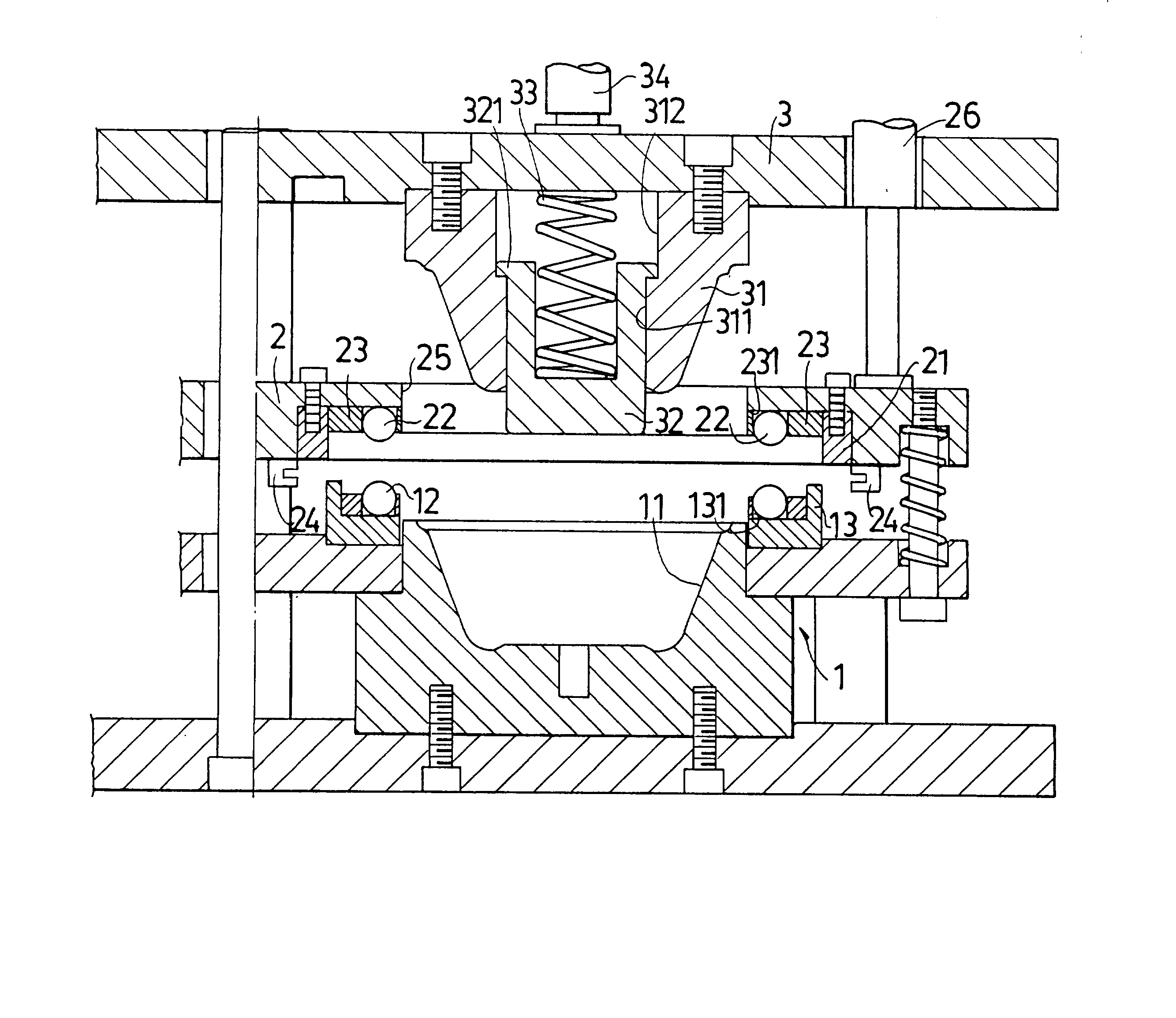
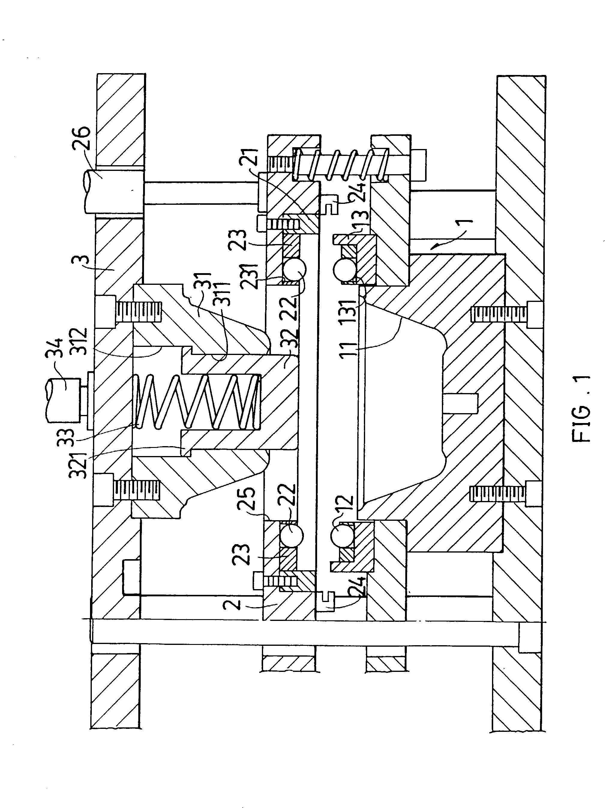
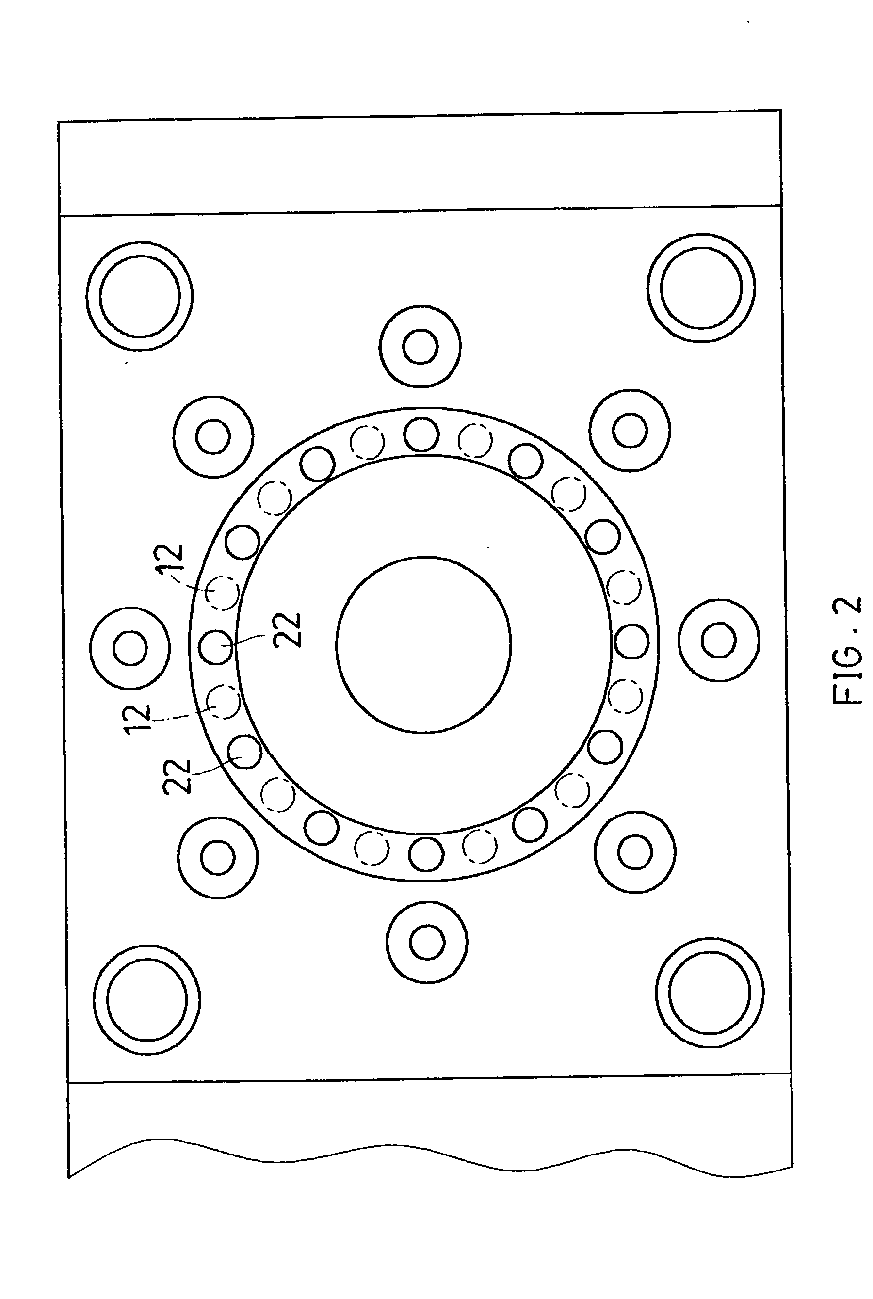
[0020] FIGS. 1 to 8 show the container manufacturing method and device of the present invention. With reference to FIGS. 1 and 2, the device includes at least one lower mold seat 1 having a mold cavity 11. Multiple protruding lower guide bodies 12 are arranged along the circumference of the mold cavity 11 at intervals. In this embodiment, the lower guide bodies 12 are steel balls 12 which are fixed on the lower mold seat 1 by a lower fixing seat 13. The lower fixing seat 13 is formed with a substantially reverse trumpet-shaped dent 131 corresponding to each steel ball 12. The steel ball 12 is rollably positioned within the dent 131. A press board 2 is disposed on the lower mold seat 1. The press board 2 is formed with a cutting section 21 corresponding to the circumference of the lower mold seat 1. Multiple protruding upper guide bodies 22 are arranged on the press board 2 and aimed at the intervals between the adjacent steel balls 12. In this embodiment, the upper guide bodies 22 a...


PUM

PropertyMeasurementUnit
circumferenceaaaaaaaaaa
shapeaaaaaaaaaa
diameteraaaaaaaaaa

Abstract

A container manufacturing method and device. The container manufacturing method includes steps of mixing, board-making, molding, guiding / crimping and demolding. Lower protruding guide bodies are arranged along the circumference of the mold cavity of the lower mold seat of the container manufacturing device at intervals. Upper protruding guide bodies are arranged on the press board and aimed at the intervals between the adjacent lower guide bodies. In the step of guiding / crimping, when the press board is pressed down by an oil pressure cylinder, the interlaced upper and lower guide bodies clamp and press the circumference of the board body to form regular crimps thereon. Therefore, when the upper mold block presses the board body into the mold cavity, the material can be evenly distributed and flowed so that the wall of the molded container can have uniform thickness.

Description

BACKGROUND OF THE INVENTION[0001] The present invention is related to a container manufacturing method and device. In a step of guiding / crimping of the container manufacturing method, the circumference of a board material is formed with regular crimps. Therefore, when the board material is tensioned, squeezed and molded by a mold into a product, the wall of the product can have uniform thickness without easy breakage.[0002] The conventional container manufacturing method includes seven steps of powdering, stirring, board-making, molding, drying, surface-treatment and further drying. The powdered chaff is mixed with an adhesive and stirred and then manufactured into a laminate material. The laminate material is twice punched and molded and heated and dried. Then the material is surface-treated and further dried.[0003] When molded, a mold is used to directly punch the laminate material into a mold cavity. When the board-like laminate material is punched into the mold cavity to have a ...

Claims


Application Information

Patent Timeline
Patent Type & Authority Applications(United States)
IPC IPC(8): B27N3/08B27N5/00
CPCB27N3/08B29C2791/001B27N5/00
Inventor DAI, WEN-LONG
Owner DAI WEN LONG
Why Eureka
Try Eureka