Crank drive for returning work pieces

a crank drive and work piece technology, applied in the direction of furnaces, furnace components, lighting and heating apparatus, etc., can solve the problems of preventing an optimal utilization of the processing unit, occupying a large amount of space alongside the processing machine, and consuming a lot of time and cos

Inactive Publication Date: 2002-12-26
LIGMATECH AUTOMATIONSSYST
View PDF0 Cites 5 Cited by
  • Summary
  • Abstract
  • Description
  • Claims
  • Application Information

AI Technical Summary

Benefits of technology

[0014] This provides for driving the lifting platform in a simpler manner using a conventional driving motor. The crank drive provides for a conversion of the rotation into a translational motion. Based on this continuous conversion of the rotation into a lifting motion, no complicated electronic equipment for transporting the work pieces is required to synchronize the lifting mechanism with the work pieces coming from the processing unit in order to increase the passage velocity.
[0015] Since the lifting movement of the lifting platform is generated by means of the crank drive, a smooth starting of the lifting mechanism is advantageously created preventing thereby that the work pieces, which lie on the lifting platform, are shifted because of their vis inertiae or, even, fall down therefrom. Following this smooth starting, the lifting motion is accelerated and, thus, a high transport velocity of the work pieces is achieved in order to achieve a sufficiently high cycle performance of the return mechanism. Thereupon, at the end of the lifting motion, the speed of work pieces is smoothly reduced by braking in order to safely transfer them to the return mechanism.
[0016] Thus, the crank drive assures a smooth starting with a high transport speed followed by a smooth subsequent reduction of speed of the work pieces lying on the platform, without complicated electric, pneumatic or hydraulic controlling being necessary. Hence, a particularly advantageous transport profile is achieved for the work pieces by simple means by the crank drive, with the course of the speed of the work pieces corresponding to the sine or cosine function by the conversion of the rotation into a translational motion.
[0020] The travelling rail preferably has hardened ridges to receive the free ends of the crank which are in particular glued-in. By this measure, the abrasion between the moving parts is reduced in order to increase the life of the device. Gluing facilitates the assembly of the ridges into the travelling rail.
[0021] The free end of the crank has advantageously a roller which may be moved in the travelling rail in longitudinal direction. By this measure, the abrasion between the end of the crank and the travelling rail is reduced, so that the efficiency of the device is increased.
[0023] In addition, it is advantageous if the crank drive is synchronized with the processing unit, which allows to further increase the cycle performance of the device, since the passage of the work pieces from the processing unit to the transfer unit and, thereupon, to the lifting platform and the return path is coordinated with each other.

Problems solved by technology

However, such a procedure is very time- and cost-consuming and prevents an optimum exploitation of the processing unit.
Such return devices, in which the return path runs substantially at the same level with the processing path and beside the same, require, on the one hand, a large amount of space alongside the processing machine.
On the other hand, the return path becomes very dirty, since finest chips or the like are continuously arising during processing in the wood working industry.
Thus, the return path needs a lot of service which is connected with great expenditure.
If a high throughput is to be achieved during processing, the design of the return mechanism and the required synchronization between processing unit and return mechanism is relatively complicated.

Method used


Image

  • Crank drive for returning work pieces
  • Crank drive for returning work pieces
  • Crank drive for returning work pieces

Examples


Embodiment Construction

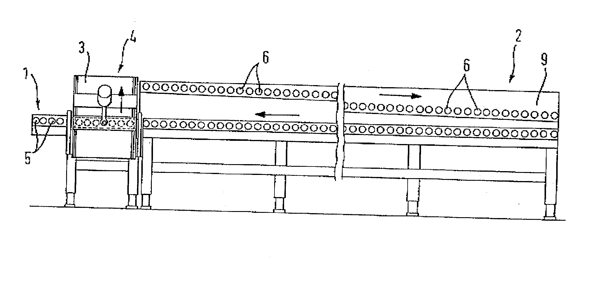
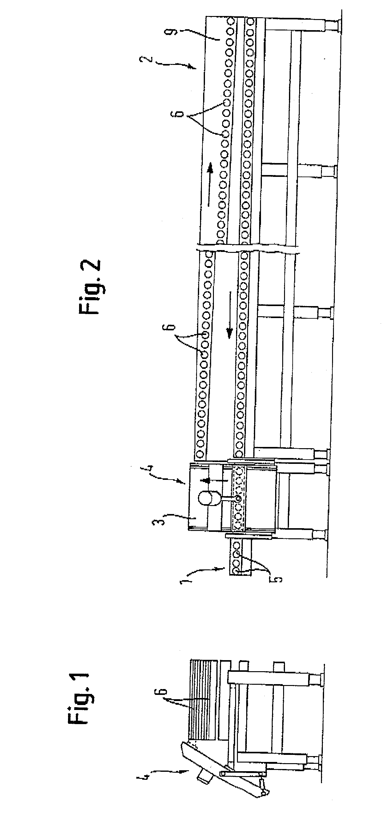
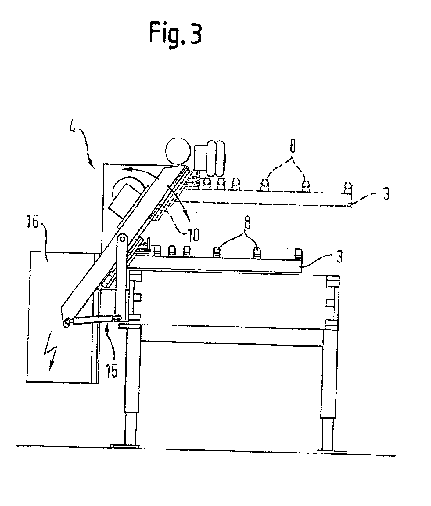
[0034] FIGS. 1 to 4 show a preferred embodiment of the mechanism of the invention for returning processed work pieces, with the mechanism being shown in FIGS. 1 and 3 as a side view and in FIGS. 2 and 4 as a rear view.

[0035] The mechanism according to the invention is attached to an already existing processing unit (not shown), for example, to an edge attachment device for pressing-in bridge edges into the edges of wooden work pieces having the form of plates. The work pieces 7 (FIG. 4) pass from the processing unit into a transfer mechanism 1 (in FIGS. 1 and 3: into the plane of the drawing, and in FIGS. 2 and 4: to the left) and are then lifted by means of a lifting mechanism with a lifting platform 3 to a return mechanism 2 which transports the work pieces 7 back to the loading side of the processing unit (in FIGS. 1 and 3: out of the plane of the drawing, and in FIGS. 2 and 4: to the right).

[0036] The lifting mechanism according to the invention has a crank drive 4 by means of w...


PUM


Abstract

The invention relates to a mechanism for returning processed work pieces (7) from the output side to the loading side of a processing unit, which mechanism has a transfer mechanism (1) to transfer the work pieces (7) at the output side of the processing unit, a return mechanism (2) for transporting work pieces (7) delivered by the transfer mechanism (1) back to the loading side of the processing unit or to a further processing unit, and a lifting mechanism to lift the work pieces (7) to a return position located above the output position, whereby the lifting mechanism is located between the transfer mechanism (1) and the return mechanism (2) and has a lifting platform (3), with the lifting mechanism having a crank drive (4), by means of which the lifting platform (3) can be raised and lowered.

Description

[0001] The invention relates to a mechanism for returning processed work pieces from the output side to the loading side of a processing unit. The mechanism has a transfer mechanism to transfer the work pieces at the output side of the processing unit, a return path for transporting work pieces delivered by the transfer mechanism back to the loading side of the processing unit or to a further processing unit, and a lifting mechanism to lift the work pieces to a return position located above the output position, which is located between the transfer mechanism and the return path and has a lifting platform.[0002] When work pieces, in particular in the form of plates, stripes or ridges are processed, which are in particular made of wood, wood-like or synthetic materials, it is often necessary to perform the processing of a work piece on a processing unit several times. In the present case, a processing unit is mainly understood to represent one or a plurality of processing stations or ...

Claims


Application Information

Patent Timeline
Patent Type & Authority Applications(United States)
IPC IPC(8): B23Q7/00B23Q7/05B65G35/06
CPCB23Q7/005Y10T74/18256B65G35/06B23Q7/05
Inventor TONNIGS, BODOKADEN, DIETMAR
Owner LIGMATECH AUTOMATIONSSYST
Why Eureka
Try Eureka