Optical systems for liquid crystal display projectors

a liquid crystal display and optical system technology, applied in the field of optical systems for liquid crystal display projectors, can solve the problems of s-p polarization shift greater, difficult trichroic prism assembly, and inability to meet the requirements of separation and recombination prisms disclosed in the prior ar

Inactive Publication Date: 2002-12-26
INTEGRATED MICRODISPLAY
View PDF0 Cites 17 Cited by
  • Summary
  • Abstract
  • Description
  • Claims
  • Application Information

AI Technical Summary

Problems solved by technology

The color separation and recombination prisms disclosed in the prior art do not meet these requirements.
At the incidence angle of 30.degree., however, the problem of s-p polarization shift is greater.
While the s-p polarization shift effect has been greatly reduced, the trichroic prism assembly is quite difficult to assemble.
Additionally, air gaps are needed in the assembly of the prisms.
Stray reflection inside the prism is quite troublesome.
This makes the back focal length of the projector lens quite long, which results in design complexity and small acceptance angles.
But the disadvantage is that half of the light will not be utilized in the image formation process.

Method used


Image

  • Optical systems for liquid crystal display projectors
  • Optical systems for liquid crystal display projectors
  • Optical systems for liquid crystal display projectors

Examples


first embodiment

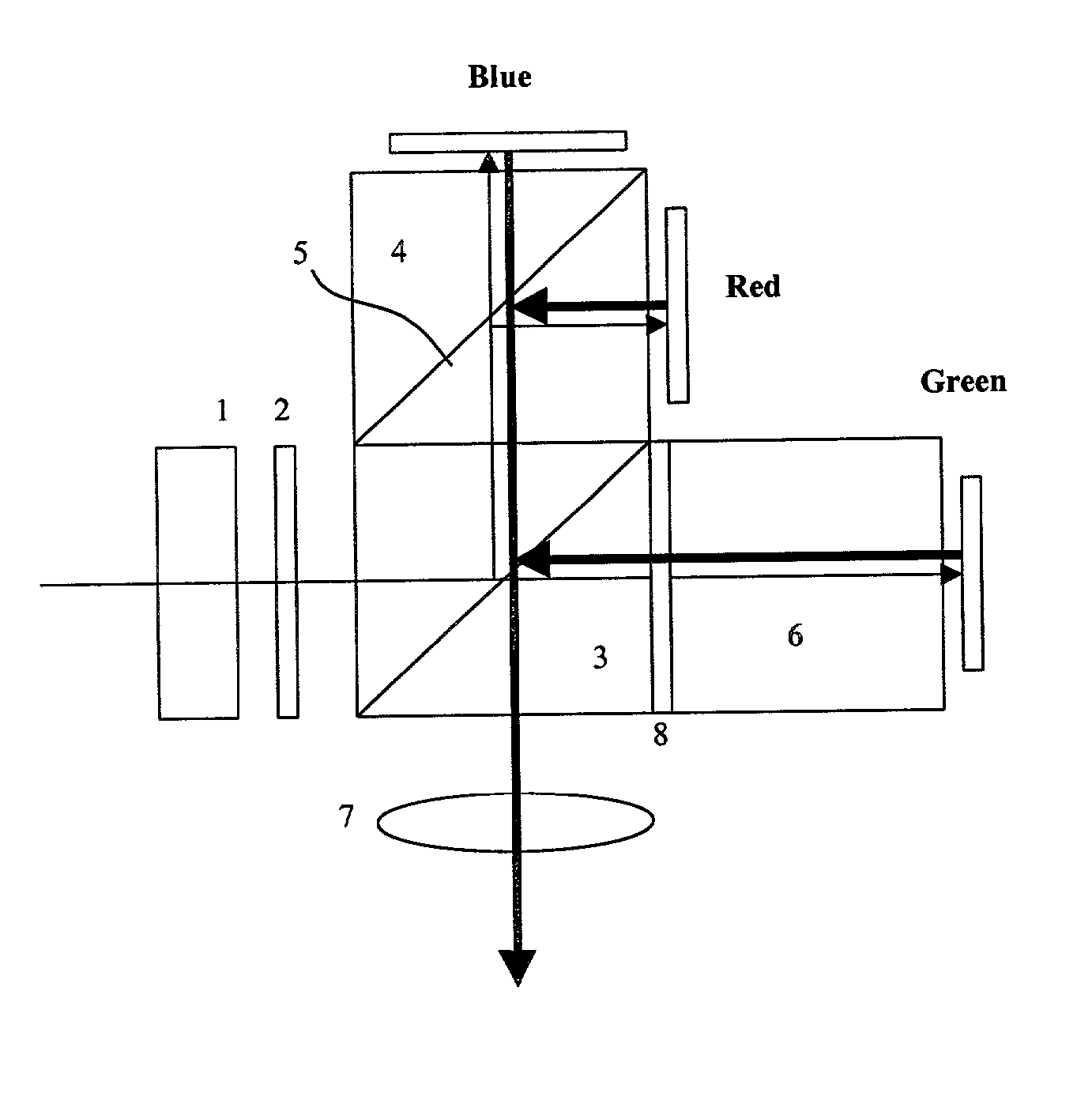
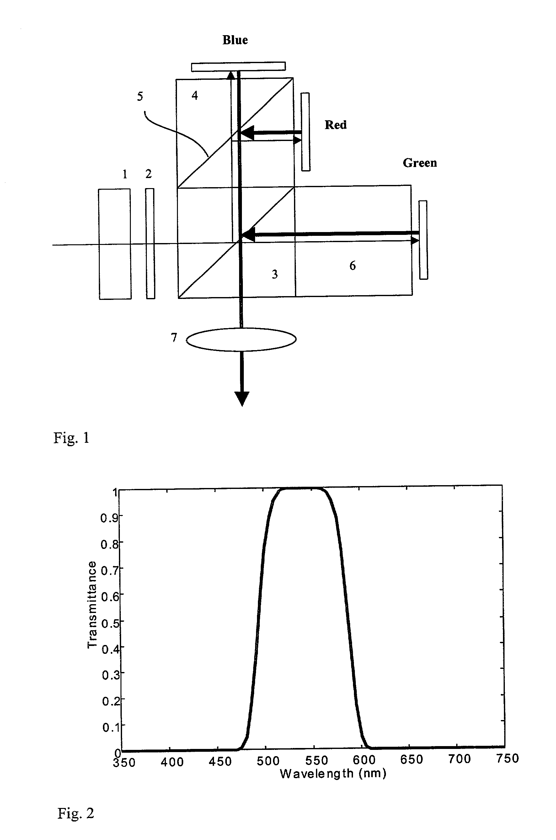
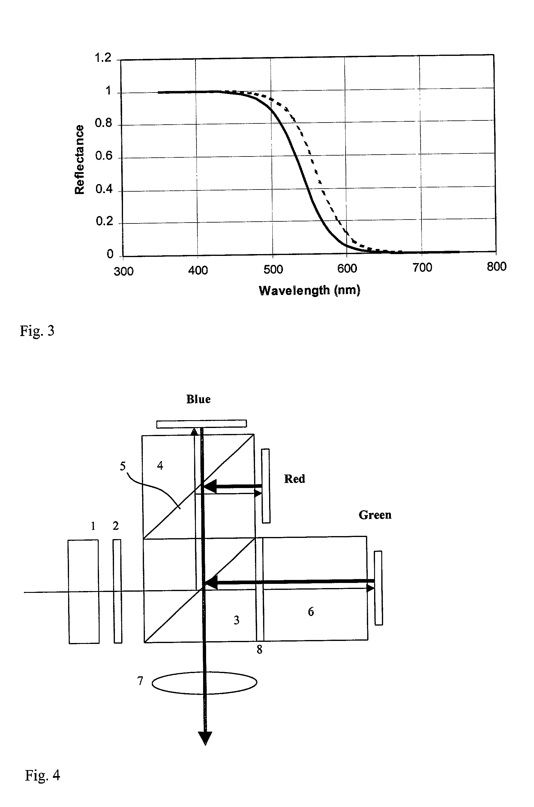
[0038] FIGS. 4-6 show 3 different variations of the present invention. The reflection direction of the color filter 5 can be to the left or right of the assembly. Additionally, the color clean-up green pass filter 8 can be used in the system.

[0039] FIGS. 7 and 8 show variation of the first embodiment. In these variations, the PBS 3 and color filter cube 4 and the glass cube 6 are replaced by different pieces of glass that minimize the total number of glass in the final assembly. In FIG. 7, a large right angle prism 9, and a small right angle prism 11, and an irregular shape prism 10 are used. In FIG. 8, the glass assembly now consists of right angle prism 11', irregular prism 10, and a parallelepiped prism 12. Right angle prisms 11' and 11 are essentially the same except for a different placement.

[0040] The second preferred embodiment of the present invention is shown in FIGS. 9-15. This embodiment is essentially the same as the first preferred embodiment except that the dichroic co...

embodiment 3

[0050] FIG. 26 shows the sixth preferred embodiment of the present invention. In this preferred embodiment, unpolarized light is used without further polarization conversion. The PBS 3 separates s- and p-polarized light into 2 equal channels. In the green channel, a green band pass filter 8 is used to pass the green light only. The green light is then modulated by the green liquid crystal light valve Green. In the other channel, an optional magenta filter 19 is used to pass blue and red light bands. A liquid crystal light valve RediBlue with on-chip color filters and subpixels for red and blue colors as used in preferred embodiment 3 is used to modulate the magenta light.

[0051] This preferred embodiment has the advantage that it is extremely simple. But the disadvantage is that only {fraction (1 / 3)} of the light is utilized.

[0052] FIGS. 27 and 28 show variations of this sixth preferred embodiment. In FIG. 27, the p-polarized light after passing through PBS 3 is filtered by a red fil...


PUM


Abstract

The present invention describes several embodiments of optical systems for the projection of images formed on reflective liquid crystal light valves. These light valves are capable of high resolution and very small sizes. The optical systems described are able to project these images with highly efficient utilization of light from an arc lamp source and are also very compact and easy to manufacture.

Description

[0001] This invention relates to novel designs for the optical system used in liquid crystal projectors. In particular, these designs relate to projectors that make use of reflective liquid crystal light valves. There are two major arrangements to be disclosed. In one arrangement, three reflective liquid crystal panels are used for full color projection displays. In the other arrangement, two liquid crystal panels are use for full color projection. In the latter case, one of the panels is used for green light and the other panel is used to modulate both blue and red lights.PRIOR ART[0002] Liquid crystal display projectors are normally based on transmittive type panels. Such liquid crystal projectors are produced commercially and many standard designs for their optical arrangements are in use. With the introduction of reflective liquid crystal light valves, the projection optics inside the projectors has to be totally redesigned. This is particularly true for full color projection di...

Claims


Application Information

Patent Timeline
Patent Type & Authority Applications(United States)
IPC IPC(8): H04N9/31
CPCH04N9/3197H04N9/3105
Inventor KWOK, HOI-SINGHUANG, HO-CHI
Owner INTEGRATED MICRODISPLAY
Why Eureka
Try Eureka