Three-dimensional photonic crystal waveguide apparatus

Inactive Publication Date: 2003-01-02
AVAGO TECH WIRELESS IP SINGAPORE PTE
View PDF0 Cites 8 Cited by
  • Summary
  • Abstract
  • Description
  • Claims
  • Application Information

AI Technical Summary

Problems solved by technology

Two-dimensional photonic crystal slab waveguide apparatus are able to guide light in a plane of the apparatus (i.e., in a plane pa

Method used


Image

  • Three-dimensional photonic crystal waveguide apparatus
  • Three-dimensional photonic crystal waveguide apparatus
  • Three-dimensional photonic crystal waveguide apparatus

Examples


Embodiment Construction

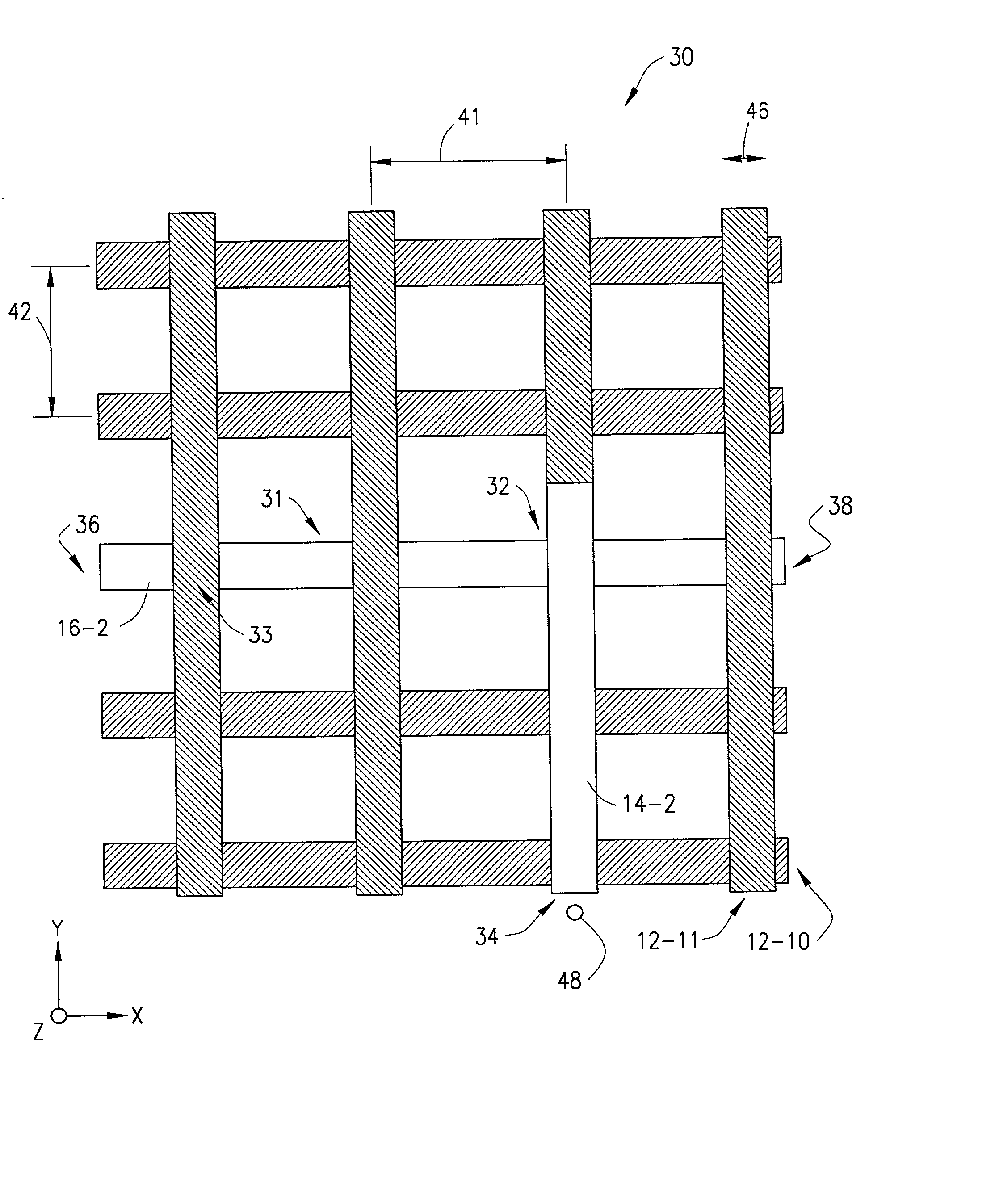
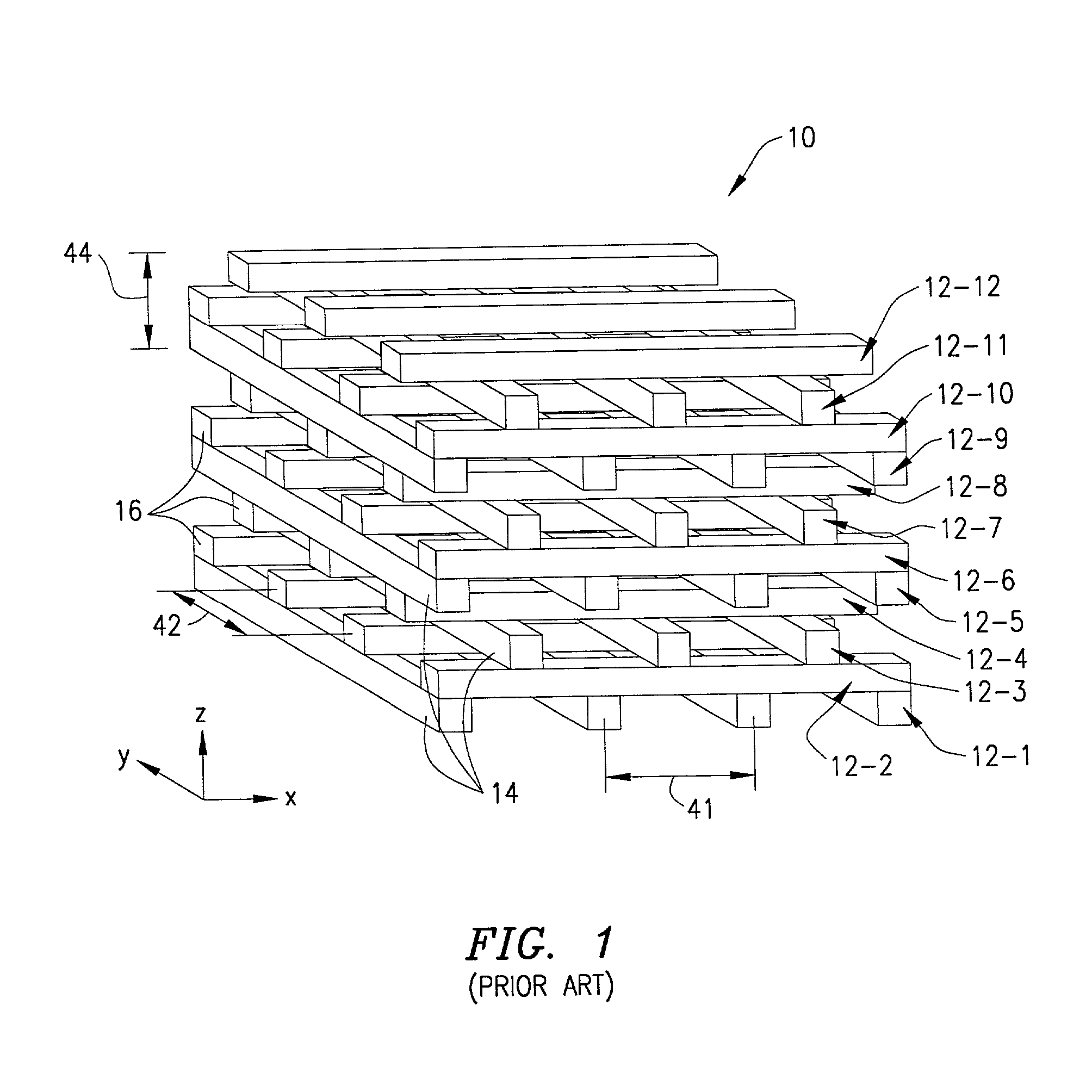
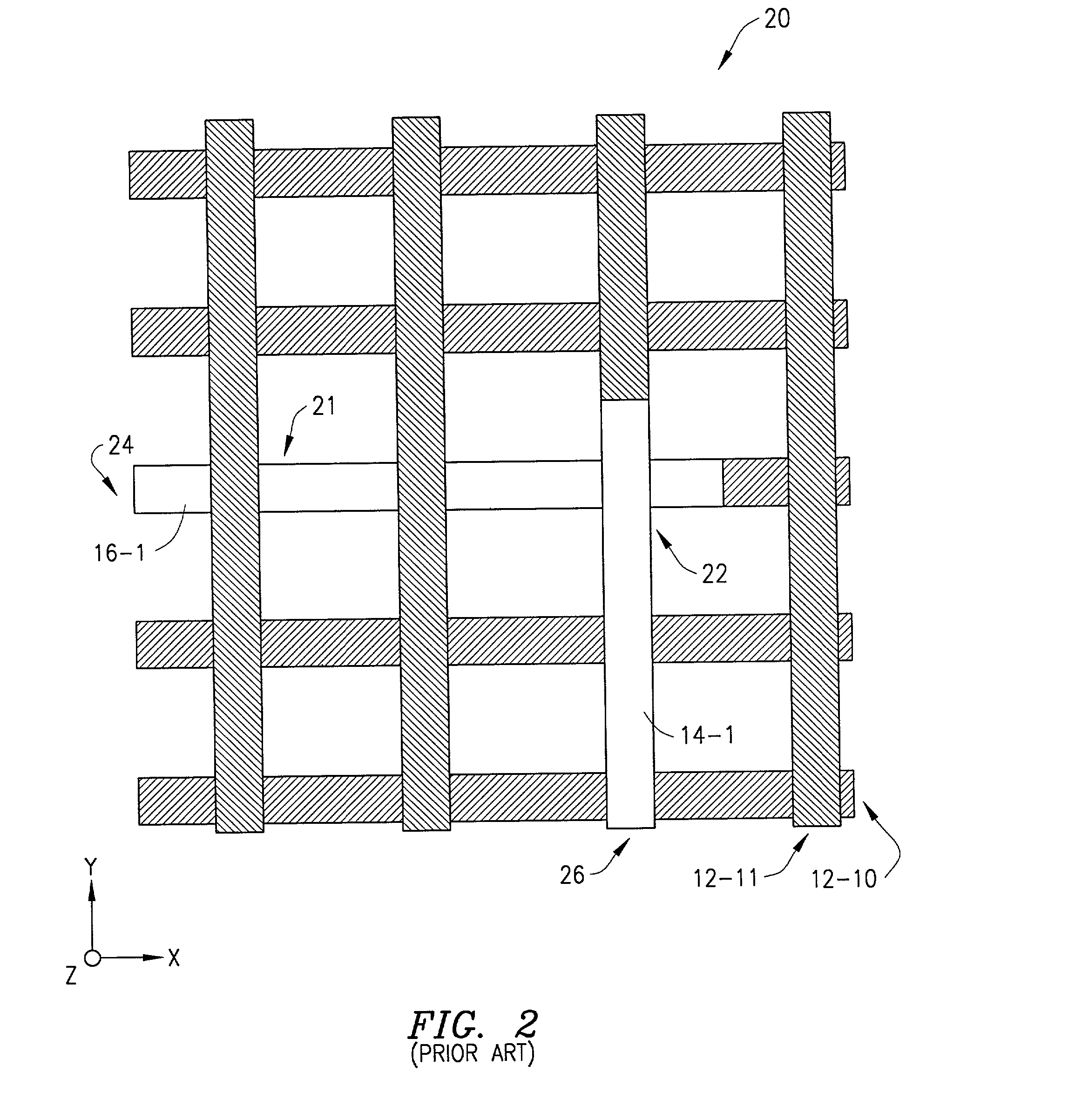
[0020] Three-dimensional photonic crystal waveguide apparatus are known in the art. In particular, FIG. 1 is a schematic, perspective view of a known three-dimensional photonic crystal apparatus (see K. M. Ho, et al., Solid State Commun., 89,413,1994 and U.S. Pat. Nos. 5,335,240 and 5,406,573) that may include an optical waveguide therein, and that is described herein to assist in explaining the present invention. The apparatus is generally designated by reference number 10 and comprises a three-dimensional photonic crystal composed of a plurality a layers arranged one on top of another. In FIG. 1, three-dimensional photonic crystal apparatus 10 comprises twelve layers 12-1 to 12-12. although the apparatus can comprise any desired plurality of layers.

[0021] Each layer 12-1 to 12-12 comprises a plurality of elements arranged to be parallel to and equally spaced from one another. In addition, the plurality of elements in each layer are arranged perpendicular to the elements in an adja...


PUM


Abstract

A three-dimensional photonic crystal waveguide apparatus has a three-dimensional photonic crystal, the three-dimensional photonic crystal having a plurality of layers arranged one above another, each of the plurality of layers having a plurality of elements that are parallel to and spaced from one another, the plurality of elements in each layer arranged at an angle other than zero with respect to the plurality of elements in an adjacent layer. The three-dimensional photonic crystal also has a waveguide therein comprising a first region of defects in a segment of an element in one layer of the plurality of layers and having a light input, and a second region of defects in at least a segment of an element in an adjacent layer of the plurality of layers and having two light outputs, the first and second region of defects intersecting to provide an optical splitter that extends from the one layer to the adjacent layer. The waveguide can be configured to guide light through the apparatus along substantially any desired path to connect different devices in a compact optical or optoelectronic integrated circuit.

Description

[0001] 1. Technical Field of the Invention[0002] The present invention relates generally to the field of photonic crystals; and, more particularly, to a three-dimensional photonic crystal waveguide apparatus.[0003] 2. Description of Related Art[0004] Photonic crystals are periodic dielectric structures that can prohibit the propagation of light in certain frequency ranges (see J. D. Joannopoulos, R. D. Meade, and J. N. Winn, Photonic Crystals, Princeton University Press, Princeton, N.J., 1995). In particular, photonic crystals have spatially periodic variations in refractive index; and with a sufficiently high refractive index contrast, photonic bandgaps can be opened in the structure's optical spectrum. The term "photonic bandgap" as used herein and as used in the art is a frequency range within which the propagation of light through the photonic crystal is prevented. In addition, the term "light" as used herein is intended to include radiation throughout the electromagnetic spectr...

Claims


Application Information

Patent Timeline
IPC IPC(8): G02B6/12G02B6/122
CPCB82Y20/00G02B6/1225
Inventor SIGALAS, MIHAIL
Owner AVAGO TECH WIRELESS IP SINGAPORE PTE
Why Eureka
Try Eureka