Method and device for solid phase microextraction and desorption

a solid phase microextraction and micro-extraction technology, applied in the direction of chemical methods analysis, chemical methods analysis, instruments, etc., can solve the problems of difficult automation, high toxicity of organic solids, time-consuming methods based on solvent extraction,

Inactive Publication Date: 2003-01-02
PAWLISZYN JANUSZ B
View PDF5 Cites 29 Cited by
  • Summary
  • Abstract
  • Description
  • Claims
  • Application Information

AI Technical Summary

Problems solved by technology

Methods based on solvent extraction are often time consuming, difficult to automate and are very expensive since they require high purity organic solvents and these organic solvents are expensive to dispose of.
Further, the organic solids usually have high toxicity and are difficult to work with.
In addition, the extraction processes can be highly non-selective.
Therefore, sequential chromatographic techniques must sometimes be used to separate complex mixtures after extraction, significantly increasing the overall analysis time and the cost.
However, solid phase extraction continues to use solvents and often suffers from high blank values.
Further, there is considerable variation between the products offered by different manufacturers and lot-to-lot variation can be a problem when carrying out solid phase extraction procedures.
Steps involving the use of organic solvents are the most time consuming.

Method used


Image

  • Method and device for solid phase microextraction and desorption
  • Method and device for solid phase microextraction and desorption
  • Method and device for solid phase microextraction and desorption

Examples


Embodiment Construction

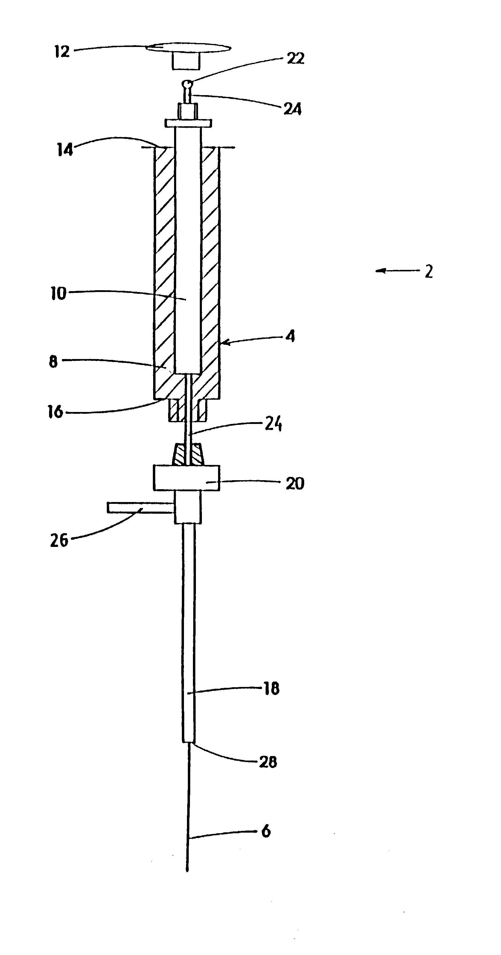
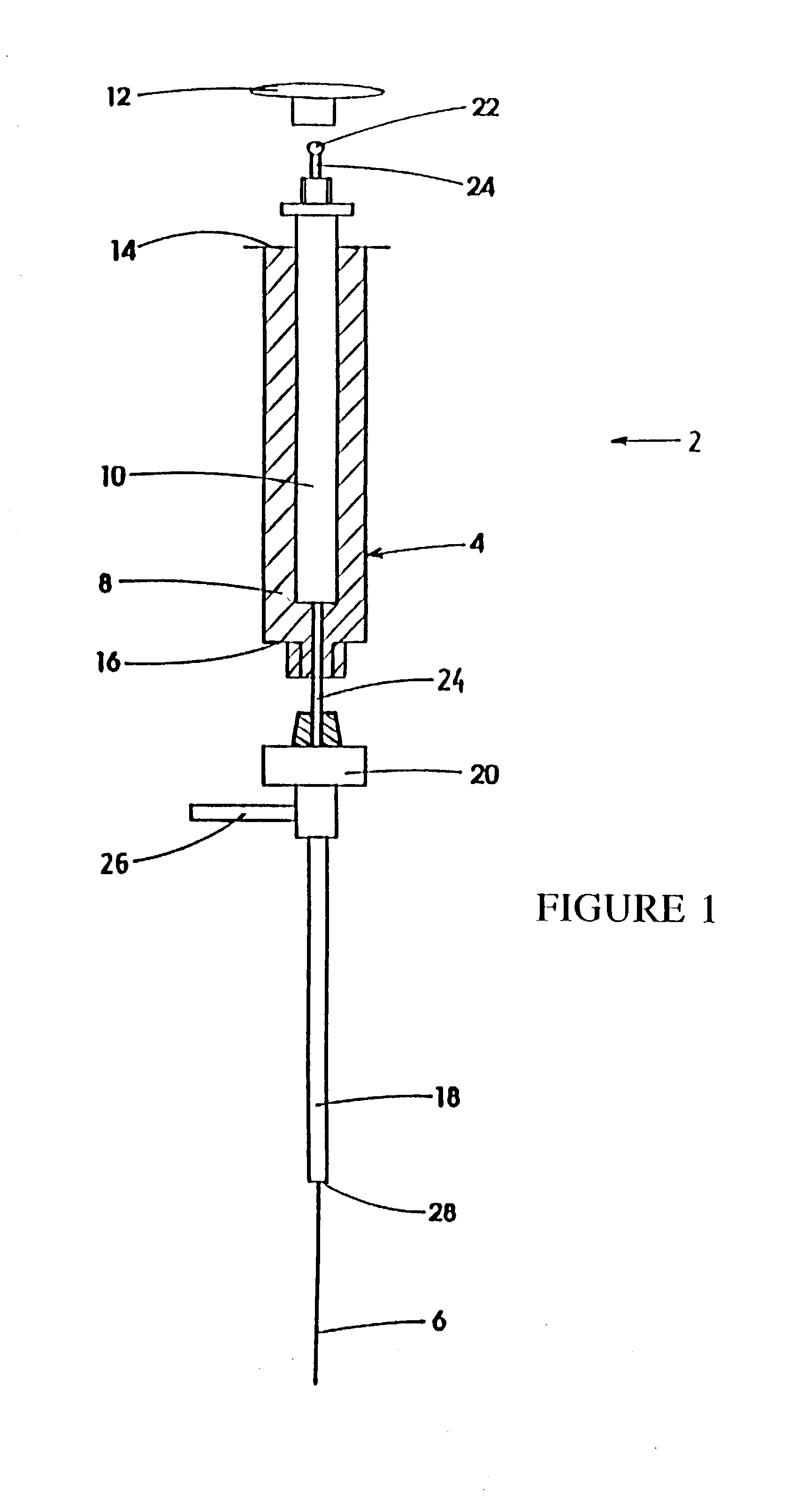
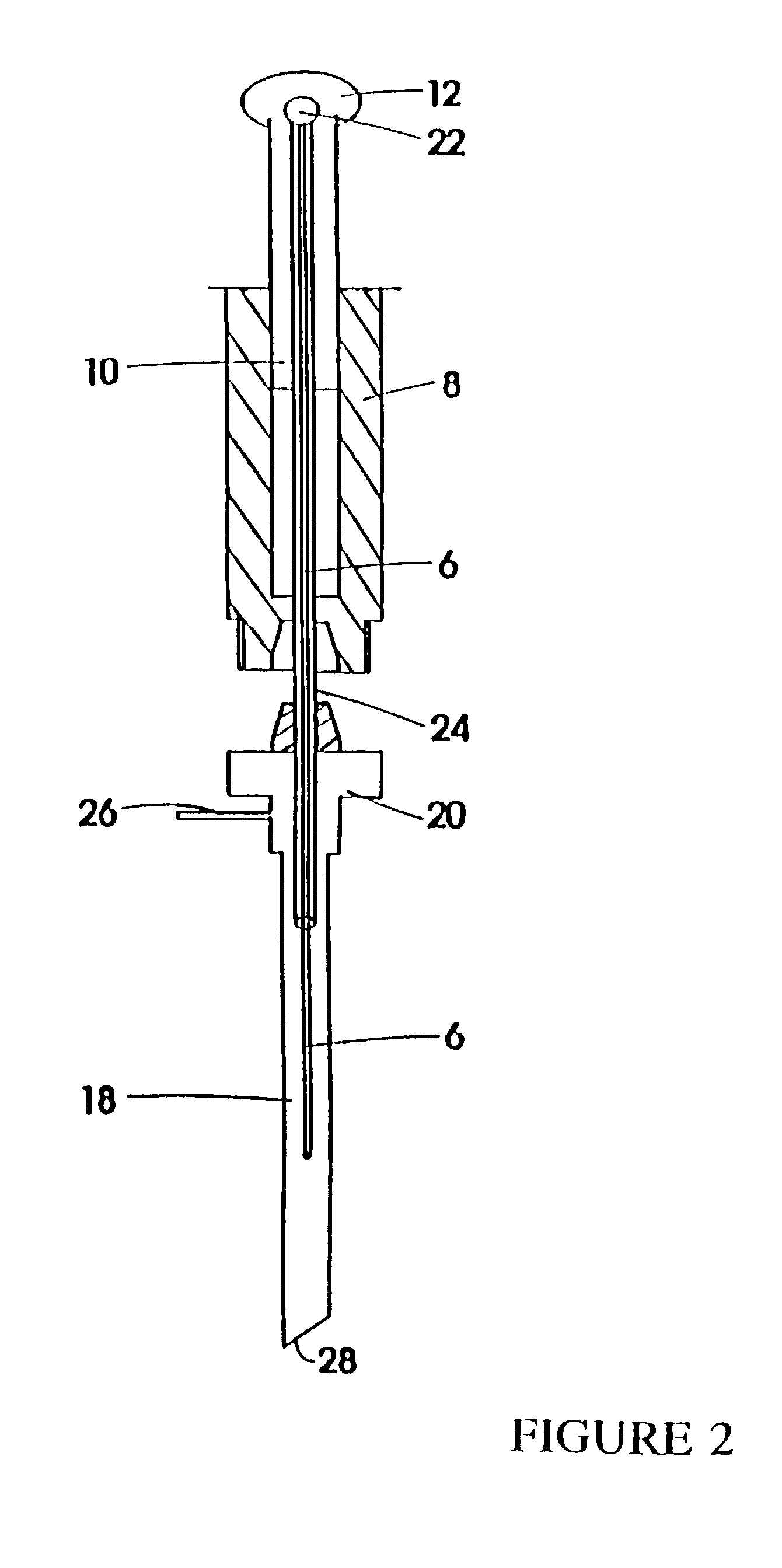
[0020] Referring to FIGS. 1 and 2 in greater detail, a device 2 for carrying out solid phase microextraction has a syringe 4 containing a fiber 6. The syringe 4 is-made up of a barrel 8 which contains a plunger 10 and is slidable within the barrel 8. The plunger 10 has a handle 12 extending from one end 14 of the barrel 8. At the opposite end 16 of the barrel 8, there is located a needle 18 which is connected to the end 16 by the connector 20. The handle 12 and the needle 18 and connector 20 are shown in an exploded position relative to the barrel 8 for ease of illustration.

[0021] The fiber 6 is a solid thread-like material that extends from the needle 18 through the barrel 8 and out the end 14. An end of the fiber 6 (not shown) located adjacent to the cap 12 has retention means 22 located thereon so that the fiber will move longitudinally as the plunger 10 slides within the barrel 8. The retention means can be simply a drop of epoxy which is placed on the end of the fiber 6 near th...


PUM

PropertyMeasurementUnit
diameteraaaaaaaaaa
diameteraaaaaaaaaa
outer diameteraaaaaaaaaa

Abstract

A device for carrying out solid phase microextraction is a fiber contained in a syringe. The fiber can be solid or hollow. The syringe has a barrel and a plunger slidable within the barrel, the plunger having a handle extending from one end of the barrel. A hollow needle extends from an end of the barrel opposite to the plunger. The fiber is contained in the needle. When the plunger is depressed, the fiber extends beyond a free end of the needle and when the plunger is in a withdrawn position, the fiber is located within the needle. The syringe protects the fiber from damage. When it is desired to analyze a sample in a bottle having a septum, the needle is inserted through the septum and the plunger is depressed so that the fiber will extend into the sample. After one or two minutes, the plunger is moved to the withdrawn position so that the fiber will return to the needle and the syringe is withdrawn from the sample bottle. The syringe is then inserted through a septum in a gas injection port of a gas chromatograph. The plunger is again depressed so that the fiber will extend into the gas chromatograph and an analysis of the components on the fiber is carried out. Then, the plunger is moved to the withdrawn and the syringe is withdrawn from the injection port. Previously, samples were analyzed using liquid-liquid extraction or using cartridges. Both of these methods are relatively expensive and time consuming. Both of these methods also require the use of solvents which can be difficult and expensive to dispose of.

Description

[0001] This is a divisional application of application Ser. No. 09 / 226,153 filed Jan. 7, 1999, which is a continuation application of application Ser. No. 08 / 826,682 filed Apr. 7, 1997, which is a continuation application of application Ser. No. 08 / 306,435 filed Sep. 19, 1994 which is a continuation-in-part Application of application Ser. No. 07 / 934,736 filed Oct. 10, 1992.[0002] 1. Field of the Invention[0003] This invention relates to a method and device for solid phase microextraction and analysis and, in particular, relates to microextraction and analysis being carried out using various types of a single fiber which can be coated with various materials or uncoated.[0004] 2. Description of the Prior Art[0005] Presently, in the organic analysis of environmental samples which involve the separation of components of interest from such matrices as soil, water, fly ash, tissue or other material, liquid extraction is traditionally used as the separation process. For example, water samp...

Claims


Application Information

Patent Timeline
Patent Type & Authority Applications(United States)
IPC IPC(8): G01N1/02G01N1/24G01N1/28G01N1/34G01N1/40G01N30/00G01N30/06G01N30/12G01N30/14G01N30/18G01N30/24G01N33/18G01N35/04G01N35/10
CPCB82Y30/00Y10T436/25875G01N1/405G01N30/12G01N30/14G01N30/18G01N30/24G01N33/18G01N2001/247G01N2001/2826G01N2030/009G01N2030/062G01N2035/0434G01N2035/1055B01J20/28014Y10T436/255G01N1/02
Inventor PAWLISZYN, JANUSZ B.
Owner PAWLISZYN JANUSZ B
Why Eureka
Try Eureka