Polarizing function element, optical isolator, laser diode module and method of producing polarizing function element

a technology of polarizing function and laser diode module, which is applied in the direction of polarizing elements, instruments, coatings, etc., can solve the problems of limiting the possibility of miniaturization, raising the product cost of optical isolators, and problems in the manufacture or the properties of these elements with polarizing functions

Inactive Publication Date: 2003-01-09
NAMIKI PRECISION JEWEL CO LTD
View PDF9 Cites 21 Cited by
  • Summary
  • Abstract
  • Description
  • Claims
  • Application Information

AI Technical Summary

Problems solved by technology

The polarizer must be interposed between the input or output side and the Faraday rotator and the relative angles must be determined precisely; this requires labor in assembly and raises the product cost of the optical isolator.
Moreover, the need for two polarizers, on both the input side and the output side of the Faraday rotator, limits the possibility of miniaturization.
There are, however, problems in the manufacture or in the properties of these elements with a polarization function.
Because the stacked structure of light-transmissive dielectric layer lattice and metallic film is simply a multiple alternation of materials, the stack is liable to separate at the metallic film if the film is made extremely thin to prevent reflective scattering of the input beam.
Because there are limits to the number of layers that can be stacked, in view of the separation at the metallic film, there are corresponding limits to the thickness in the direction of stacking, and so it is not possible to input a beam with a large beam diameter.
When the Faraday rotator is cut, damages or impurities can occur easily in the polarizing film because of irregularities in the intervals between metallic lattice segments, an

Method used


Image

  • Polarizing function element, optical isolator, laser diode module and method of producing polarizing function element
  • Polarizing function element, optical isolator, laser diode module and method of producing polarizing function element
  • Polarizing function element, optical isolator, laser diode module and method of producing polarizing function element

Examples


Embodiment Construction

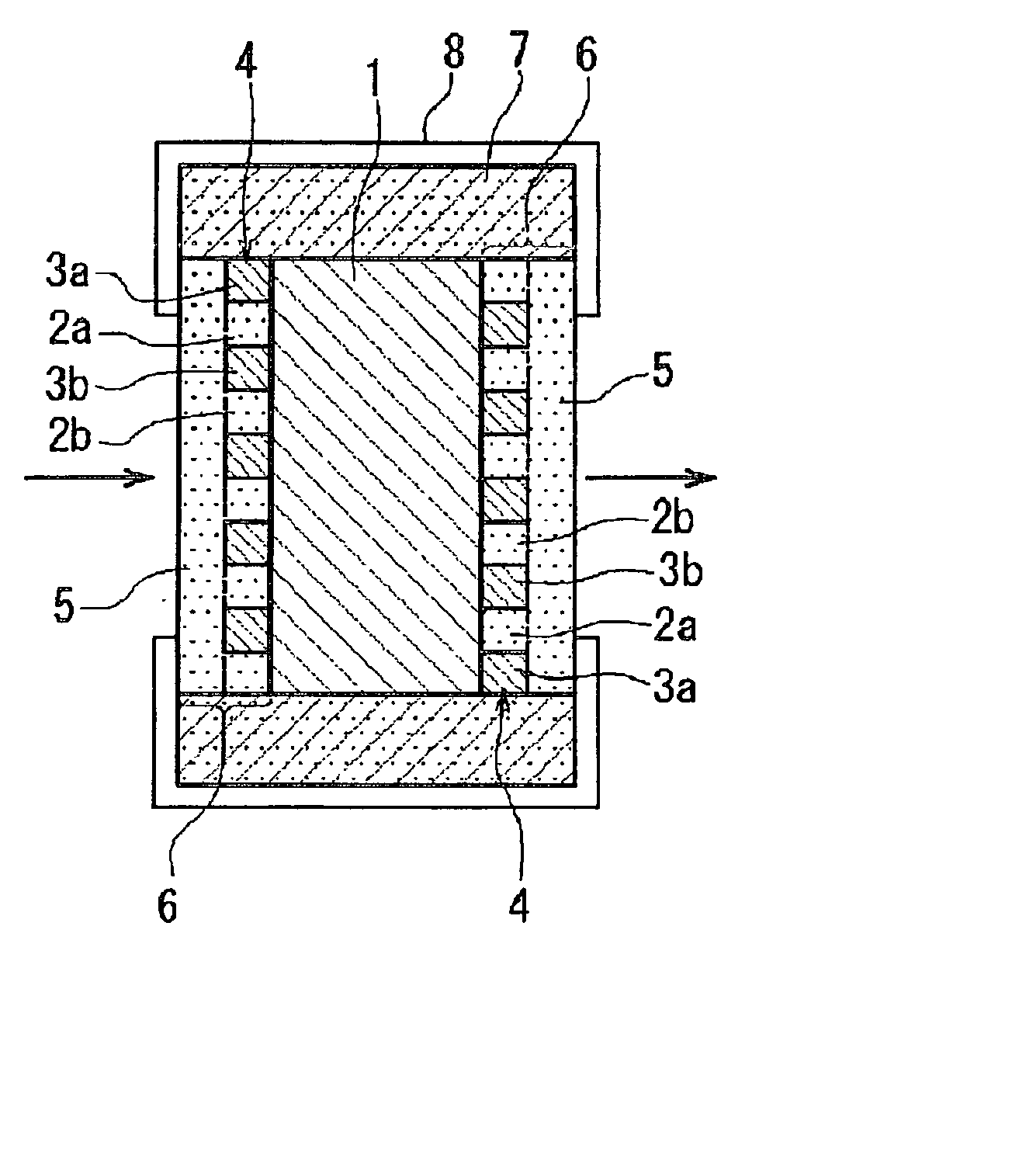
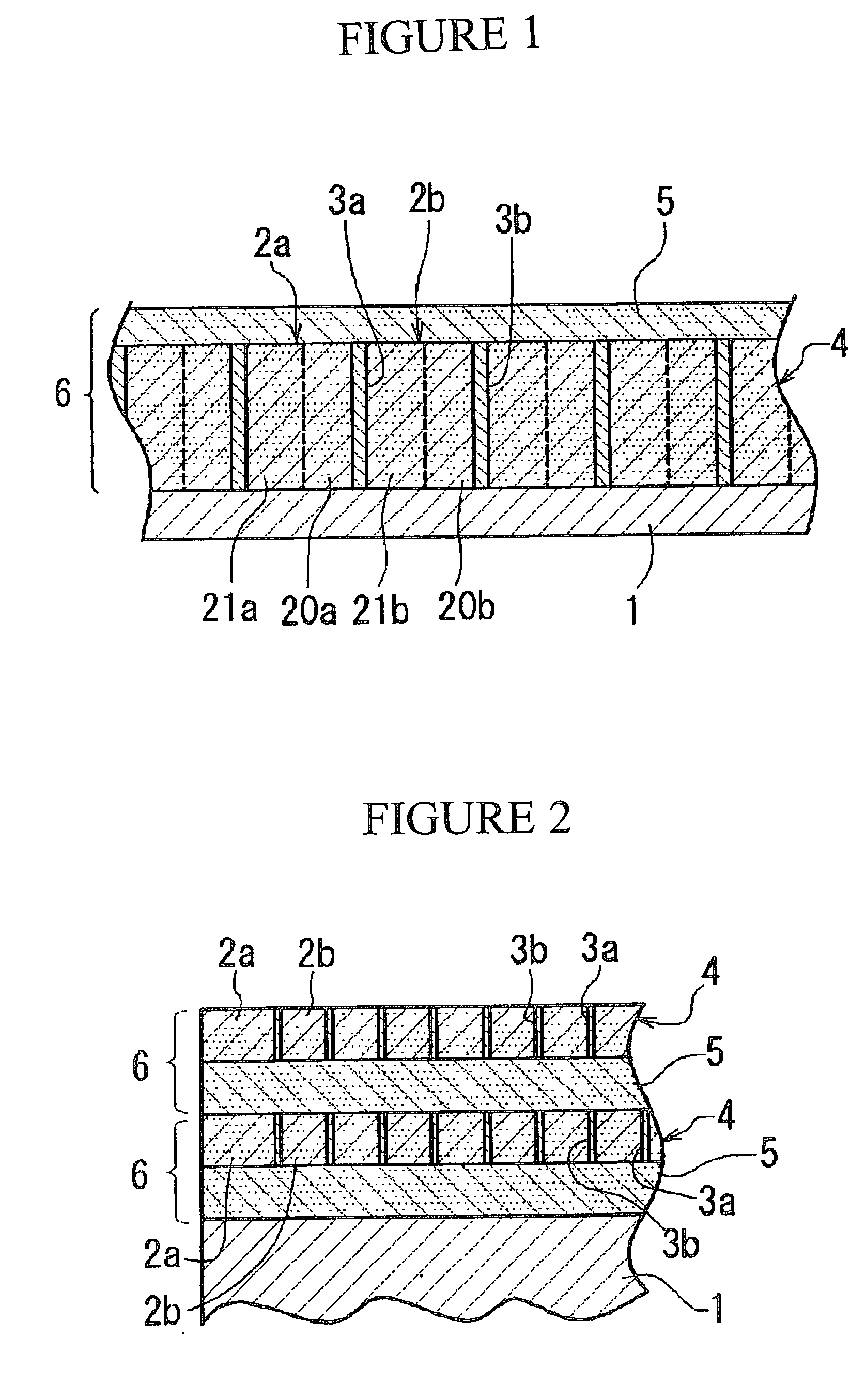
[0016] This invention has a polarizing portion with a striped structure formed by multiple alternating light-transmissive dielectric layers and metallic film layers, which has both the polarizing function of polarizing an input beam and a non-reflecting function of suppressing reflection of the input beam, and is formed at least on one side of a light-transmissive substrate. By integrating the polarizing portion, as the polarizing and non-reflective film, with the light transmissive substrate in this way, it is possible to have the polarizing and non-reflective film and the substrate in a strong, integrated structure, and to have superior performance including light-transmissivity and polarization.

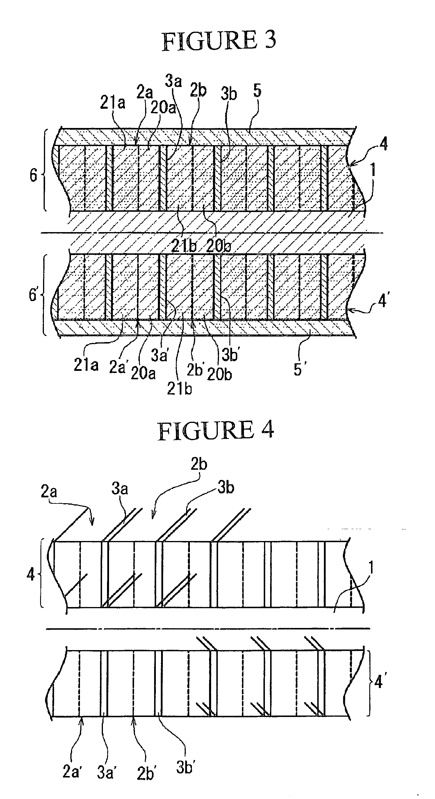
[0017] It is also possible to improve the performance as a polarizing function element and increase the polarization / extinction ratio by forming a polarizing portion or stacked portion on both sides of the light-transmissive substrate.

[0018] It is preferable that the metallic film layers b...


PUM

PropertyMeasurementUnit
Fractionaaaaaaaaaa
Thicknessaaaaaaaaaa
Sound / signal amplitudeaaaaaaaaaa

Abstract

This invention has the polarizing function of polarizing an input beam and a non-reflecting function of suppressing reflection of the input beam, wherein at least one side of a light-transmissive substrate 1 has a polarizing portion 4 with a striped structure formed by multiple alternating light-transmissive dielectric layers 2a, 2b . . . and metallic film layers 3a, 3b . . . . Its characteristics are improved if the metallic film layers are very thin and flat, with a target thickness in the range from 5 to 20 nm and variation of film thickness within the range of ±10%.

Description

FIELD OF INDUSTRIAL USE[0001] This invention concerns a polarizing function element, an optical isolator and a laser diode module. It also concerns a method of producing the polarizing function element.PRIOR ART[0002] An optical isolator normally has as its constituent parts, at the least, a Faraday rotator, polarizers on the beam input and output sides, and a magnet to provide a parallel magnetic field in the direction of the beam axis. In this constitution, a polarizing prism or polarizing glass is used as the polarizer. The polarizer must be interposed between the input or output side and the Faraday rotator and the relative angles must be determined precisely; this requires labor in assembly and raises the product cost of the optical isolator. Moreover, the need for two polarizers, on both the input side and the output side of the Faraday rotator, limits the possibility of miniaturization.[0003] Polarizing function elements of various construction have been proposed to reduce th...

Claims


Application Information

Patent Timeline
IPC IPC(8): G02B1/11G02B5/20G02B5/30
CPCG02B1/11G02B5/204G02B5/3025Y10S359/90
Inventor IMAIZUMI, NOBUOSHIROKI, KENICHIKASAI, YOSHIHITOSATO, TOSHIMICHI
Owner NAMIKI PRECISION JEWEL CO LTD
Why Eureka
Try Eureka