Eureka AIR delivers breakthrough ideas for toughest innovation challenges, trusted by R&D personnel around the world.

High-speed web-splicing tape and method of use thereof

a websplicing tape and high-speed technology, applied in the direction of film/foil adhesives, instruments, photosensitive materials, etc., can solve the problems of disrupting and damaging the machinery of industrial applications, labor intensive and time-consuming, and affecting the performance of so as to prevent damage to the reel or the machinery involved, the effect of sufficient strength

Inactive Publication Date: 2003-01-16
SPECIALITY TAPES DIV OF RSW
View PDF0 Cites 24 Cited by
  • Summary
  • Abstract
  • Description
  • Claims
  • Application Information

AI Technical Summary

Benefits of technology

[0013] Another object of the invention is to provide a tape for use in high-speed web-splices which prevents damage to either reel or to the machinery involved in web handling.
[0017] Yet another object of the invention is to provide a high-speed web-splicing tape which allows for quick application to a reel and preparation for splicing.
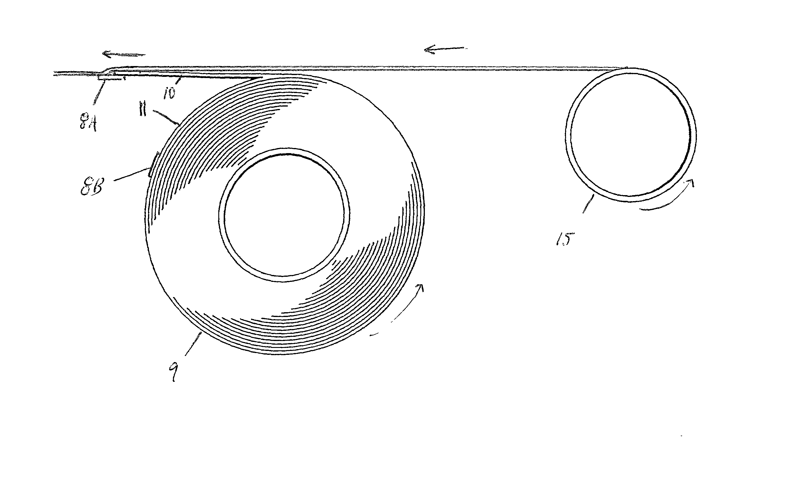
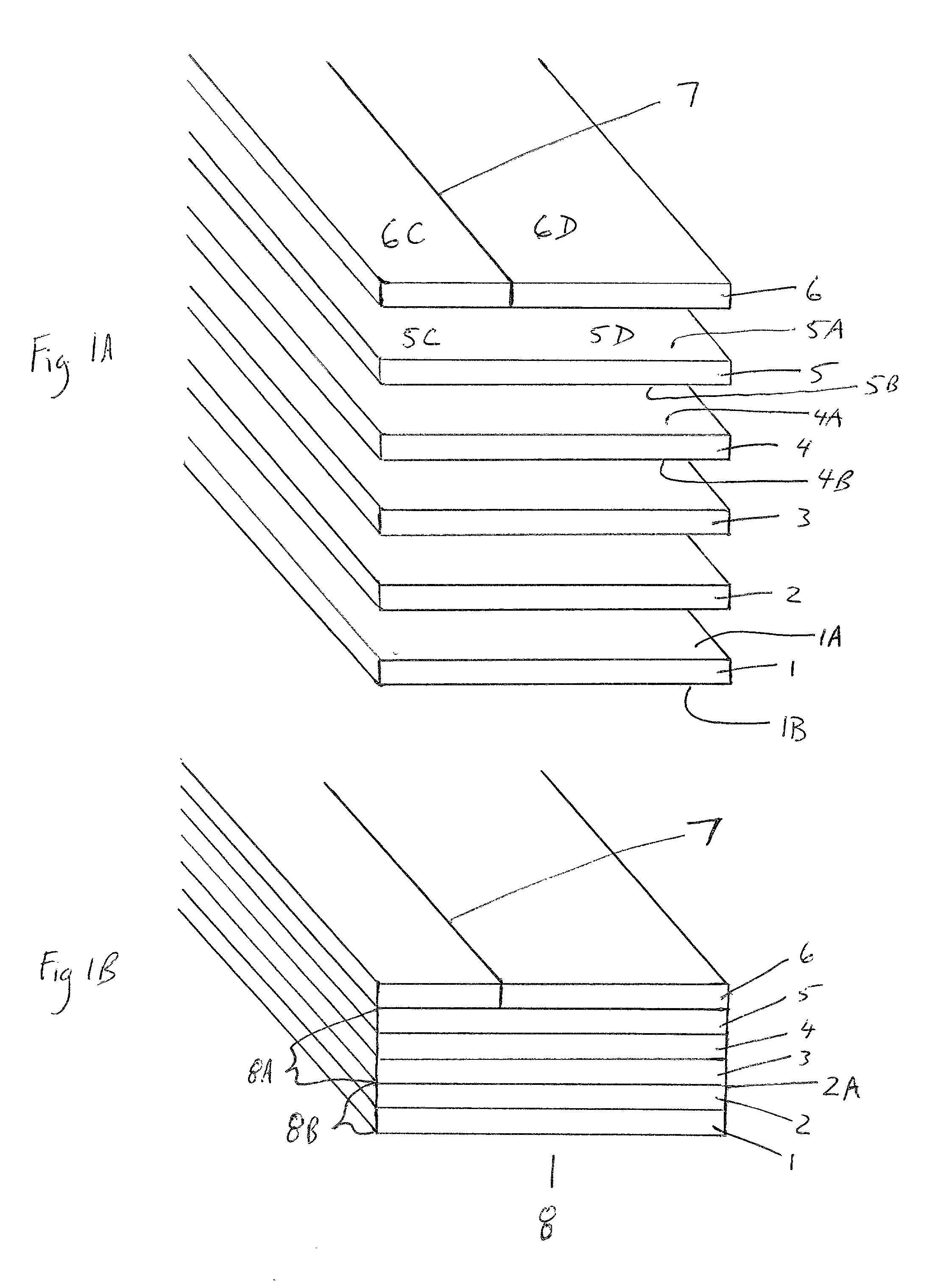
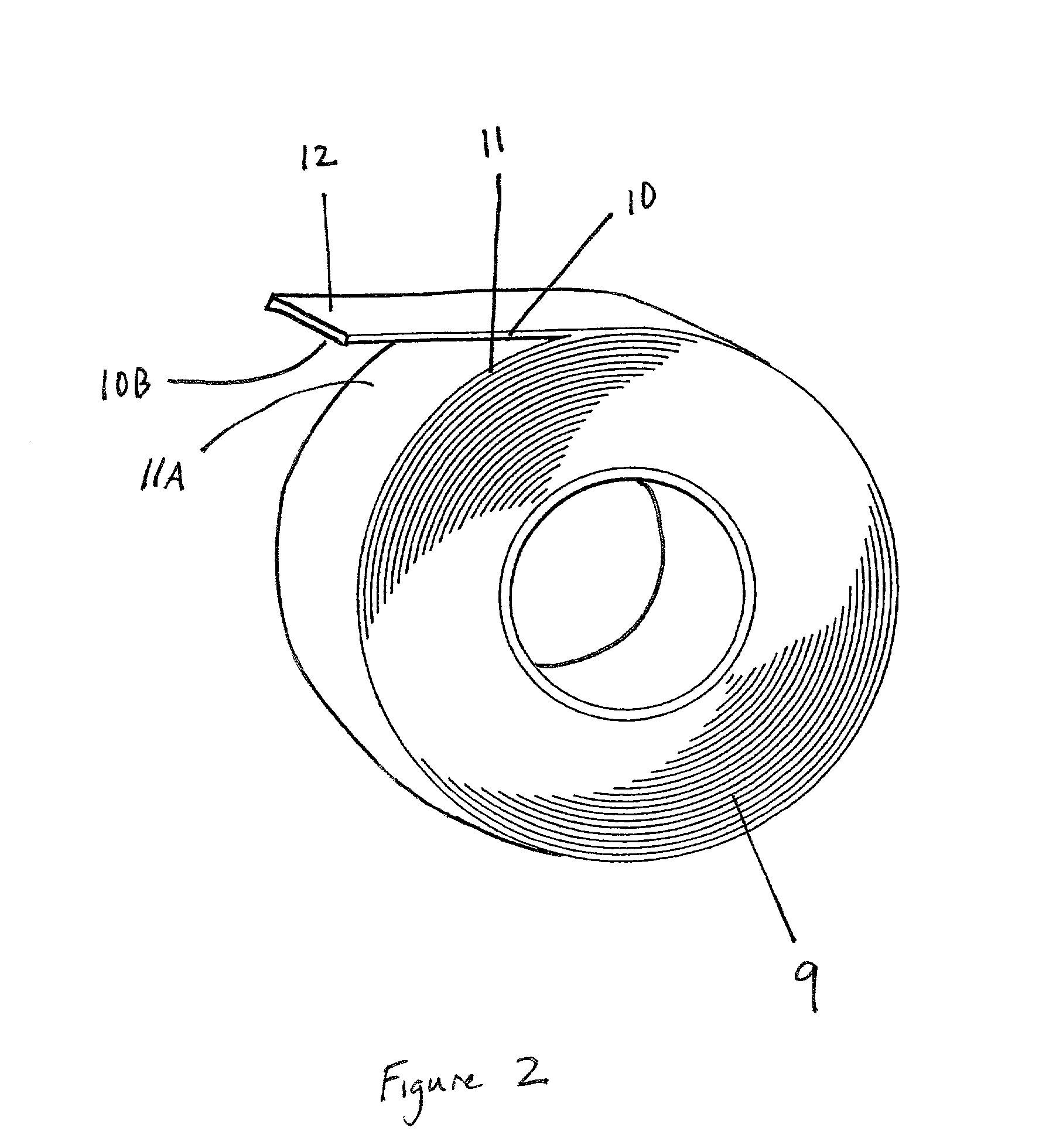
[0020] The new high-speed web-splicing tape and method of use thereof are intended to provide for reliable, efficient high-speed web-splicing requiring less labor, time and repair. The new high-speed web-splicing tape for use in high-speed flying reel splices between a reel (roll) of a depleted web and a reel (roll) of a new web, the new web having an outer layer (10) with an inner surface (10B) and an inner layer (11) with an outer surface (11 A). The tape includes: a first adhesive (1) having top (1A) and bottom (1B) surfaces; a breakaway-coating (2) covering the top surface (1A); a release-coating (3) affixed to the breakaway-coating (2) along an interface; a substrate (4) having first (4A) and second (4B) surfaces, the second surface (4B) secured to the release-coating (3); and a second adhesive (5) having upper (5A) and lower (5B) surfaces, the lower surface (5B) adhered to the first surface (4A) and the upper surface (5A) having proximal (5C) and distal (5D) portions. The tape, having been adhered to the new web through adhesion of the bottom surface (1B) to the outer surface (11A) and adhesion of the proximal portion (5C) to the inner surface (10B) and having adhesive which is exposed at the distal portion (5D), separates along the interface of the release-coating (3) and breakaway-coating (2) when the distal portion (5D) is contacted and adhered to the depleted web, such that the first adhesive (1) and breakaway-coating (2) continue to adhere to the outer surface (11A) and the release-coating (3), substrate (4) and second adhesive (5) adhere to both the inner surface (10B) and the depleted web so that no adhesive is exposed after separation.

Problems solved by technology

These applications typically involve numerous web-splices, which are labor intensive and time consuming.
Several problems are associated with flying reel splices.
This process is extremely time consuming and labor intensive.
Due to the application and separation of the tabs, adhesive surfaces of the tab were exposed and could disrupt and damage the machinery of the industrial application.
Even without exposure of adhesive, the presence of unadhered portions of tabs could disrupt and damage the machinery.
Thus, this prior art method of providing for high-speed web-splicing did not address all problems associated with the process.
Such exposed adhesive can disrupt and severely damage the expensive machinery involved in web handling.
While these patents addressed some of the problems of the prior art, they present additional problems.
However, in practice the paper often does not cleave so perfectly resulting in exposed adhesive and damage to the machinery.
Furthermore, the paper-backed tape is not strong enough to use in high-speed web-splices due to the inherent strength limitation of paper and the preferred use of paper which will split along its middle when normal splice force is applied.
In addition, the ragged surface of the cleaved paper layer may cause disruptions in, and damage to, the expensive web handling machinery.
Finally, the paper layers involved in these patents accept and reject moisture, are susceptible to humidity and encounter storage problems when experiencing high temperatures.
These factors can lead to curling and wrinkling of the reel and problems in web handling.

Method used


Image

  • High-speed web-splicing tape and method of use thereof
  • High-speed web-splicing tape and method of use thereof
  • High-speed web-splicing tape and method of use thereof

Examples


Embodiment Construction

[0036] Referring to the figures, details of the high-speed web-splice tape and method of use will be set forth. FIG. 1A-1B depict a cross sectional view of the novel tape. First adhesive 1 has a bottom surface 1B and top surface 1A. Top surface 1A is covered by breakaway-coating 2. Release-coating 3 is affixed to breakaway-coating 2 along an interface 2A. Substrate 4 has a first surface 4A and a second surface 4B and is secured to release-coating 3 along second surface 4B. Second adhesive 5 has an upper surface 5A and a lower surface 5B which is adhered to first surface 4A of substrate 4. Upper surface 5A is adhered to release liner 6. Release liner 6 has a mechanical weakness 7 which is slit running parallel to the edges of the tape. Mechanical weakness 7 divides release liner 6 into first portion 6C and second portion 6D. First portion 6C is secured to proximal portion 5C of second adhesive 5. Second portion 6D is secured to distal portion 5D of second adhesive 5. First adhesive 1...


PUM

PropertyMeasurementUnit
Thicknessaaaaaaaaaa
Thicknessaaaaaaaaaa
Thicknessaaaaaaaaaa

Abstract

An adhesive tape for use in high-speed web-splicing which provides for adherence of the loose end of a web reel to the reel before allowing the tape to separate along a specific interface between two non-adhesive layers upon connection to a depleted web. The separation of tape along the specific interface results in the absence of any exposed adhesive surfaces.

Description

[0001] This invention relates generally to splicing tapes and, in particular, to tapes for use in flying web splices of the type involving joining the web of a new reel to the web of a depleted reel.[0002] Web-splicing is a common process encountered in many industrial applications. The process is typically used in the printing or coating of paper or other substrates and other applications in the film and paper industry. These applications typically involve numerous web-splices, which are labor intensive and time consuming.[0003] During the web-splicing process, the loose end or tail of a wound reel of material is adhered or otherwise attached to the web of reel already in use. Due to the depletion of the reel in use, a web-splice must be performed in order to allow for the continuation or the printing or coating application. In order to alleviate the time lost during the connection of the new reel to the depleted reel, it is known in the prior art to connect these reels while the p...

Claims


Application Information

Patent Timeline
IPC IPC(8): B31F5/06B65H19/10B65H19/28C09J7/20
CPCB31F5/06B65H19/102B65H19/28B65H2301/4607B65H2301/46078C09J7/02C09J2203/342C09J7/20
Inventor STARKEY, JOHN
Owner SPECIALITY TAPES DIV OF RSW
Why Eureka
Eureka Blog
Learn More