Soundproof cover

a sound insulation layer and cover technology, applied in the direction of fuel intake silencers, combustion air/fuel air treatment, instruments, etc., can solve the problems of increased manufacturing cost, difficult to securely inhibit the sound insulation layer from vibrating, and the sound insulation layer itself makes a noise source when it vibrates

Inactive Publication Date: 2003-01-16
SUMITOMO RIKO CO LTD +1
View PDF0 Cites 34 Cited by
  • Summary
  • Abstract
  • Description
  • Claims
  • Application Information

AI Technical Summary

Problems solved by technology

However, since the sound insulation layer is usually formed as a hard plate shape, there is a drawback in that the sound insulation layer itself makes a noise source when it vibrates.
Yet, in the conventional soundproof covers, it has been difficult to securely inhibit the sound insulation layers from vibrating so that the sound insulation layers themselves do not make a noise source in a case where the noise source vibrates considerably.
Accordingly, there arises a problem in that the manufacturing cost goes up.
Consequently, there arises a problem in that the assembly workability is impaired.
When the compression hardness is less than 100 N/314 cm.sup.2, the sound waves are likely to pass through the sealing layer so that there might arise a drawback in that the sounds leak out in a case where the sealing layer is formed of foamed polyurethane.
Consequently, it might be difficult for such a sealing layer to absorb the fluctuations in the dimensions and the fluctuations in the positions du

Method used


Image

  • Soundproof cover
  • Soundproof cover
  • Soundproof cover

Examples


Embodiment Construction

[0036] The present invention will be hereinafter described in detail with reference to an example and a testing sample.

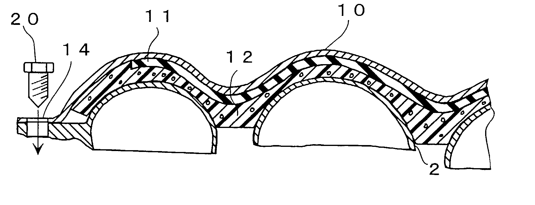
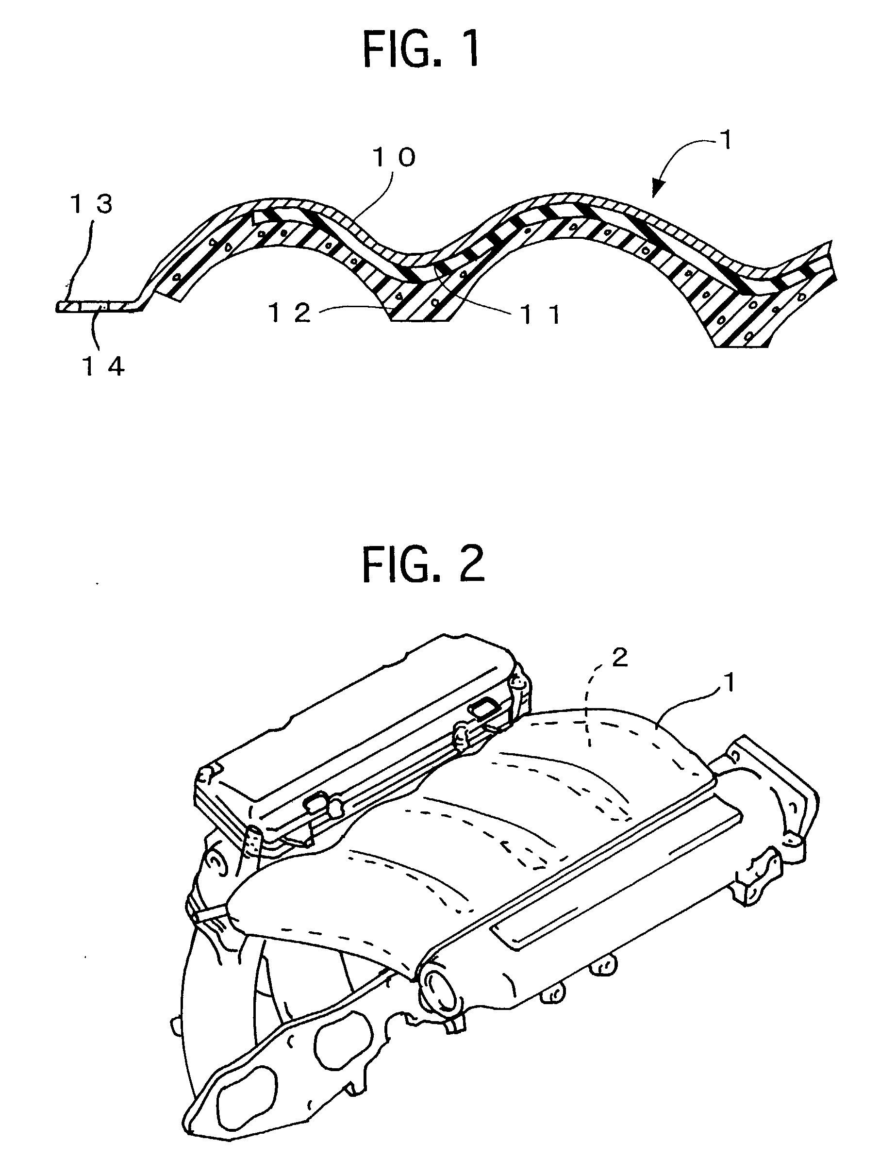
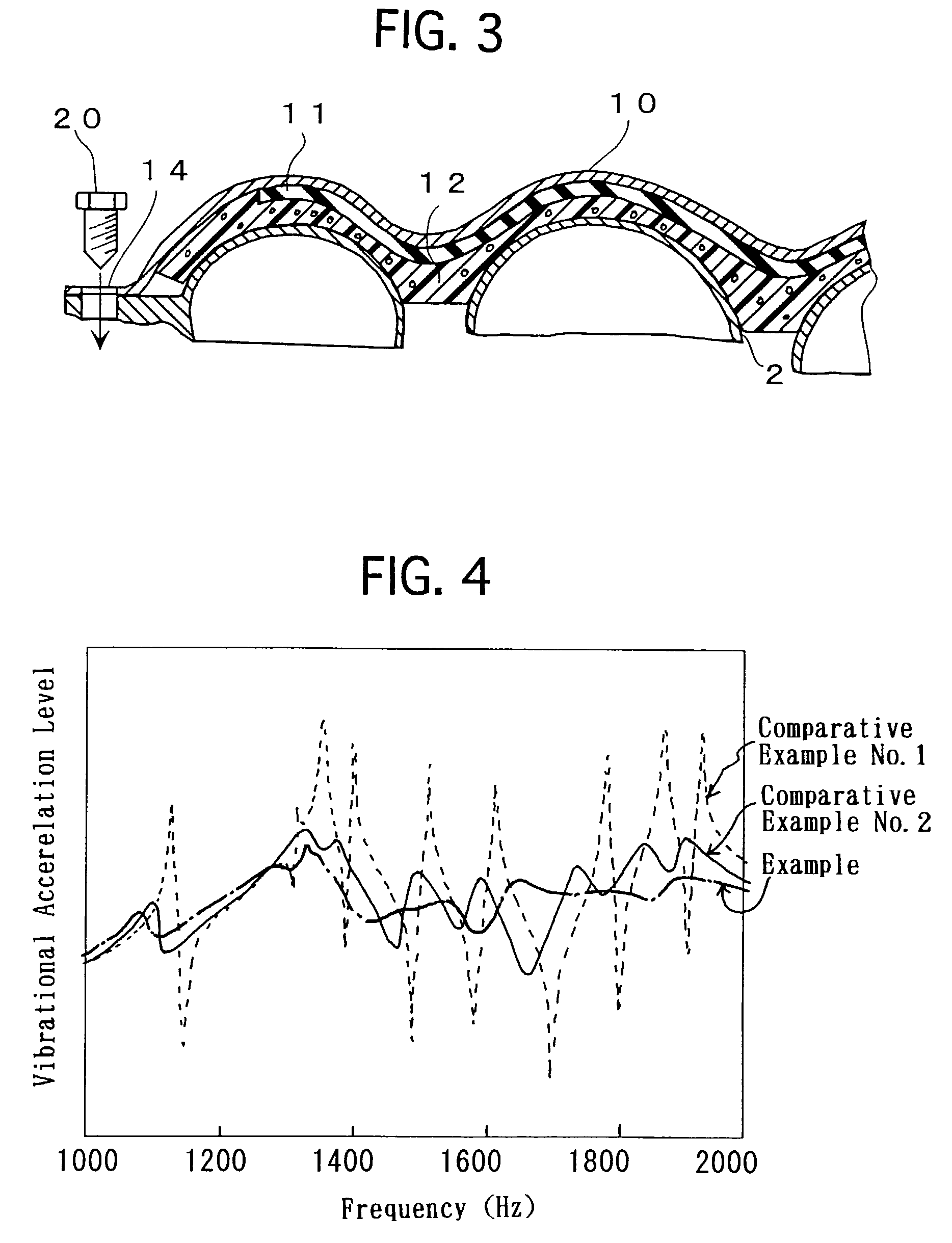
[0037] FIG. 1 illustrates a cross sectional view of a soundproof cover according to an example. FIG. 2 illustrates a perspective view of the soundproof cover in service. FIG. 3 illustrates a major cross sectional view of FIG. 3. The soundproof cover is fastened to an automotive intake manifold to use.

[0038] As illustrated in FIG. 1, the soundproof cover 1 comprises a sound insulation layer 10, a vibration inhibition layer 11 and a sealing layer 12. The sound insulation layer 10 is made of a coated steel plate. The vibration inhibition layer 11 is laminated on one of opposite surfaces of the sound insulation layer 10, and is made of rubber. The sealing layer 12 is laminated on the opposite surface of the sound insulation layer 10 as well as on one of opposite surfaces of the vibration inhibition layer 11, and is made of foamed polyurethane.

[0039] A manufacturing proc...


PUM

PropertyMeasurementUnit
Energyaaaaaaaaaa
Elasticityaaaaaaaaaa
Elastic modulusaaaaaaaaaa

Abstract

A soundproof cover includes a sealing layer, a sound insulation layer, and a vibration inhibition layer. The sound insulation layer has a peripheral portion, is to be disposed so as to contact at least the peripheral portion with a noise source, and exhibits elasticity. The sound insulation layer is formed as a hard plate shape, has an installation portion to be fastened to the noise source, and is disposed so as to cover the sealing layer. The vibration inhibition layer is disposed on at least a part of an interface between the sealing layer and the sound insulation layer so as to adhere to the sound insulation layer, and inhibits the sound insulation layer from vibrating.

Description

[0001] 1. Field of the Invention[0002] The present invention relates to a soundproof cover which is disposed to a noise source, such as an intake manifold of an automobile, and which can inhibit noises by insulating sounds being generated by the noise source.[0003] 2. Description of the Related Art[0004] Automobiles comprise many vibrating component members in which engines are principal one of such component members. To reduce the noises, which are generated by their vibrations, is one of the assignments to automobile engineers. Hence, it has been carried out disposing soundproof covers, which cover the noise sources. For example, in Japanese Unexamined Patent Publication (KOKAI) No. 10-205,352, there is disclosed a soundproof cover, which is constituted by a hard sound insulation layer and a sound absorption layer. The hard sound insulation layer is formed of a resin or steel plate. The sound absorption layer is laminated on one of opposite surfaces of the sound insulation layer w...

Claims


Application Information

Patent Timeline
IPC IPC(8): F02B77/13F02M35/10F02M35/12G10K11/16G10K11/162G10K11/168
CPCF02M35/10301F02M35/10321F02M35/10334F05C2225/08G10K11/168F02M35/1272F02M35/1277
Inventor MIYAKAWA, SHINJIUEMATSU, SATOSHI
Owner SUMITOMO RIKO CO LTD
Why Eureka
Try Eureka