In-band and out-of-band signal detection for automatic gain calibration systems

Inactive Publication Date: 2003-01-16
QUALCOMM INC
View PDF0 Cites 63 Cited by
  • Summary
  • Abstract
  • Description
  • Claims
  • Application Information

AI Technical Summary

Problems solved by technology

In such receivers, less amplifier gain is needed for strong signals, and it is important that a very strong signal not be amplified to

Method used


Image

  • In-band and out-of-band signal detection for automatic gain calibration systems
  • In-band and out-of-band signal detection for automatic gain calibration systems
  • In-band and out-of-band signal detection for automatic gain calibration systems

Examples


Embodiment Construction

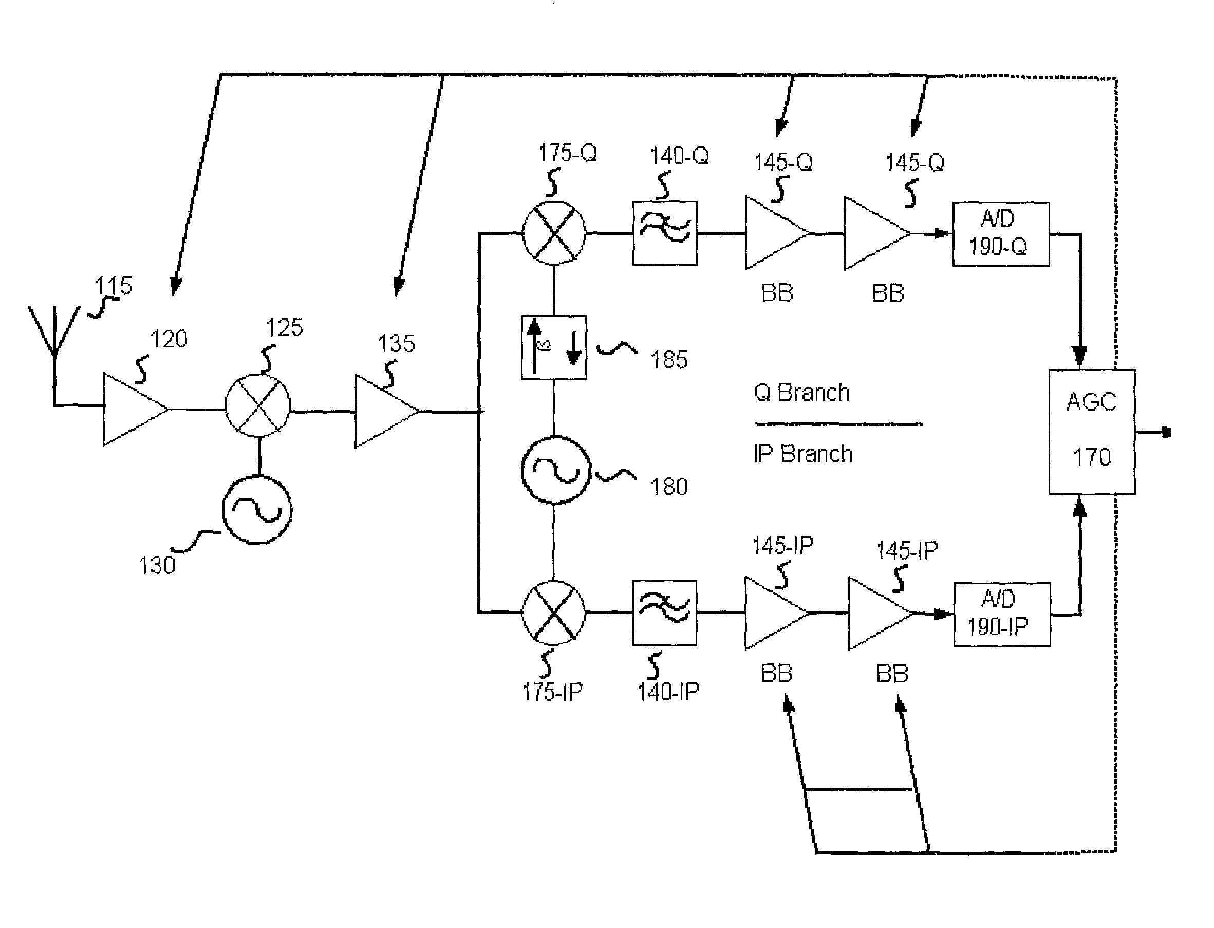
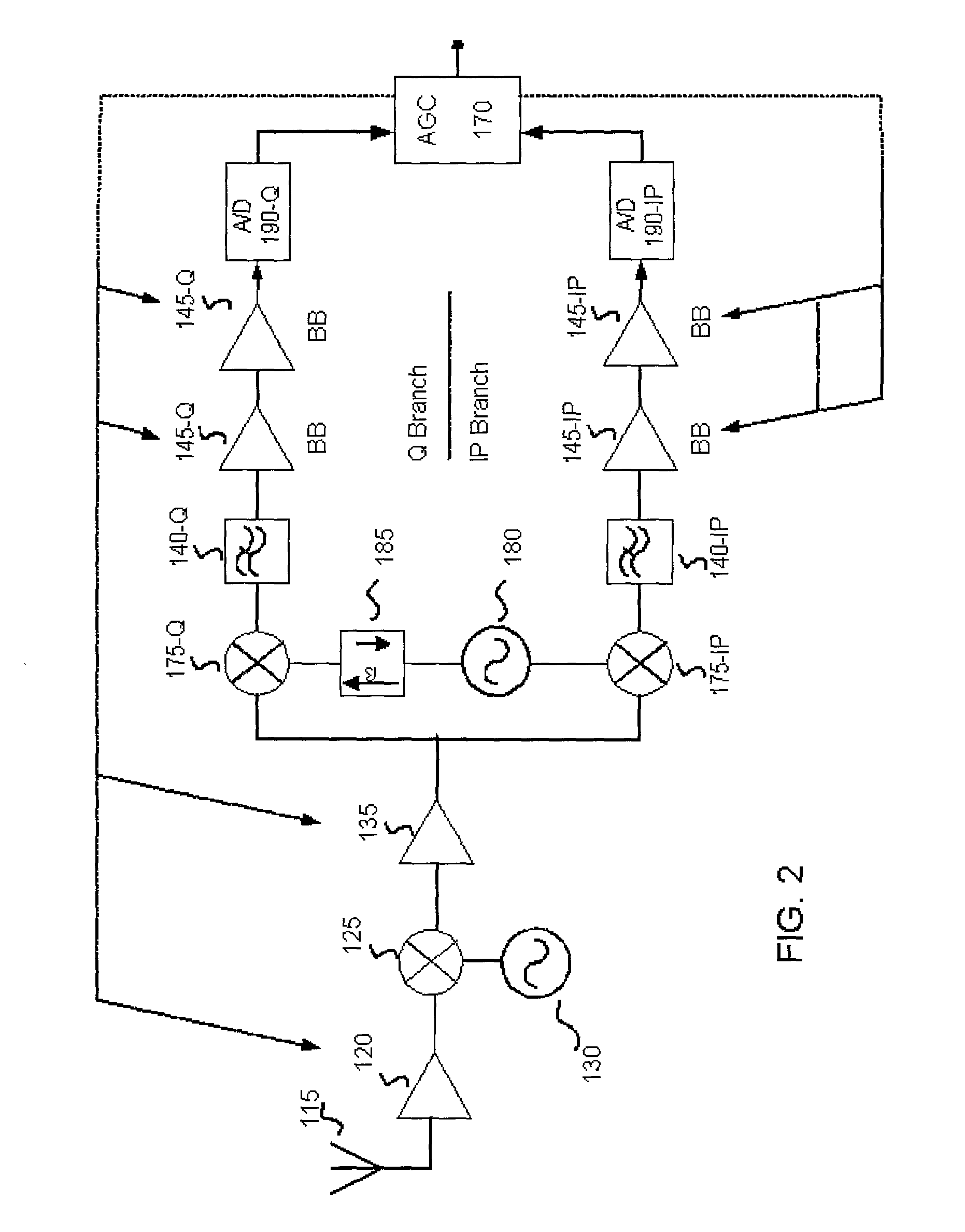
[0014] The basic structure of a receiver of an embodiment of the present invention is shown in FIG. 2. Here, a wideband antenna 115 receives a radio frequency (RF) RF signal and provides it to an RF amplifier 120, and a particular channel or signal within the band is preferably selected by varying the local oscillators 130 and 180. In the embodiment, the RF signal preferably conforms to the IEEE 802.11a standard, has a frequency in the 5 GHz band and is quadrature modulated to carry 6 to 54 Mbps. In this embodiment, the signal can carry up to 54 Mbits of data and lies within one of twelve 20 MHz wide slots, eight within a 5.151-5.35 GHz band and four within a 5.75-5.85 GHz band. The signal in this embodiment is a coded orthogonal frequency division multiplexed (OFDM) signal using 52 subcarriers spaced 312.5 kHz apart. It is understood, however, that while the following detailed description of the present invention is made in the context of an IEEE 802.11a system, that the inventions...


PUM


Abstract

An embodiment of the present invention provides an automatic gain control system for a wireless receiver that quickly differentiates desired in-band signals from high power out-of-band signals that overlap into the target band. The system measures power before and after passing a received signal through a pair of finite impulse response filters that largely restrict the signal's power to that which is in-band. By comparing the in-band energy of the received signal after filtering to the total signal energy prior to filtering, it is possible to determine whether a new in-band signal has arrived. The presence of this new in-band signal is then verified by a multi-threshold comparison of the normalized self-correlation to verify the presence of a new, desired in-band signal.

Description

[0001] 1. Field of the Invention[0002] The present invention is directed to communication systems. More particularly, the invention is directed to receivers in wireless communication systems. Even more particularly, the present invention is directed to automatic gain control systems for such wireless communication system receivers.[0003] 2. Background of the Related Art[0004] The use of receivers in wireless systems such as radio and cellular communication systems is well-known in the art. FIG. 1 shows a typical superheterodyne receiver design 10. Here, a radio frequency (RF) signal is received on antenna 15 and provided to RF amplifier 20. The RF signal is amplified by the RF amplifier 20 and in mixer 25 mixed with a signal from a local oscillator 30. This produces an intermediate frequency (IF) signal that is amplified in an IF amplifier 35 and filtered in a bandpass filter 40. The filtered IF signal is again amplified by an IF amplifier 45 and mixed in a product detector 50 with ...

Claims


Application Information

Patent Timeline
IPC IPC(8): H03G5/16H04B1/10
CPCH03G5/165H04B1/1036H04B1/109
Inventor HUSTED, PAULTHON, LARS E.MCFARLAND, WILLIAMNG, TAO FEI SAMUEL
Owner QUALCOMM INC
Why Eureka
Try Eureka