Optical disk apparatus with flexible capacity by adjustment of recording density

a technology of optical disk and recording density, which is applied in the direction of digital signal error detection/correction, instruments, recording signal processing, etc., can solve the problems of troublesome disk selection operation, inconvenient operation of purchasing cd-r with the corresponding capacity, and insufficient recording area of 100 mb

Inactive Publication Date: 2003-01-30
YAMAHA CORP
View PDF10 Cites 62 Cited by
  • Summary
  • Abstract
  • Description
  • Claims
  • Application Information

AI Technical Summary

Problems solved by technology

The disk selecting operation is troublesome, and further the user needs to prepare various types of CD-R disks beforehand.
Moreover, when there is not available a CD-R having an appropriate recording capacity, laborious works of purchasing the CD-R having the corresponding capacity has to be performed.
However, in the conventional operation, when da...

Method used


Image

  • Optical disk apparatus with flexible capacity by adjustment of recording density
  • Optical disk apparatus with flexible capacity by adjustment of recording density
  • Optical disk apparatus with flexible capacity by adjustment of recording density

Examples


case 1

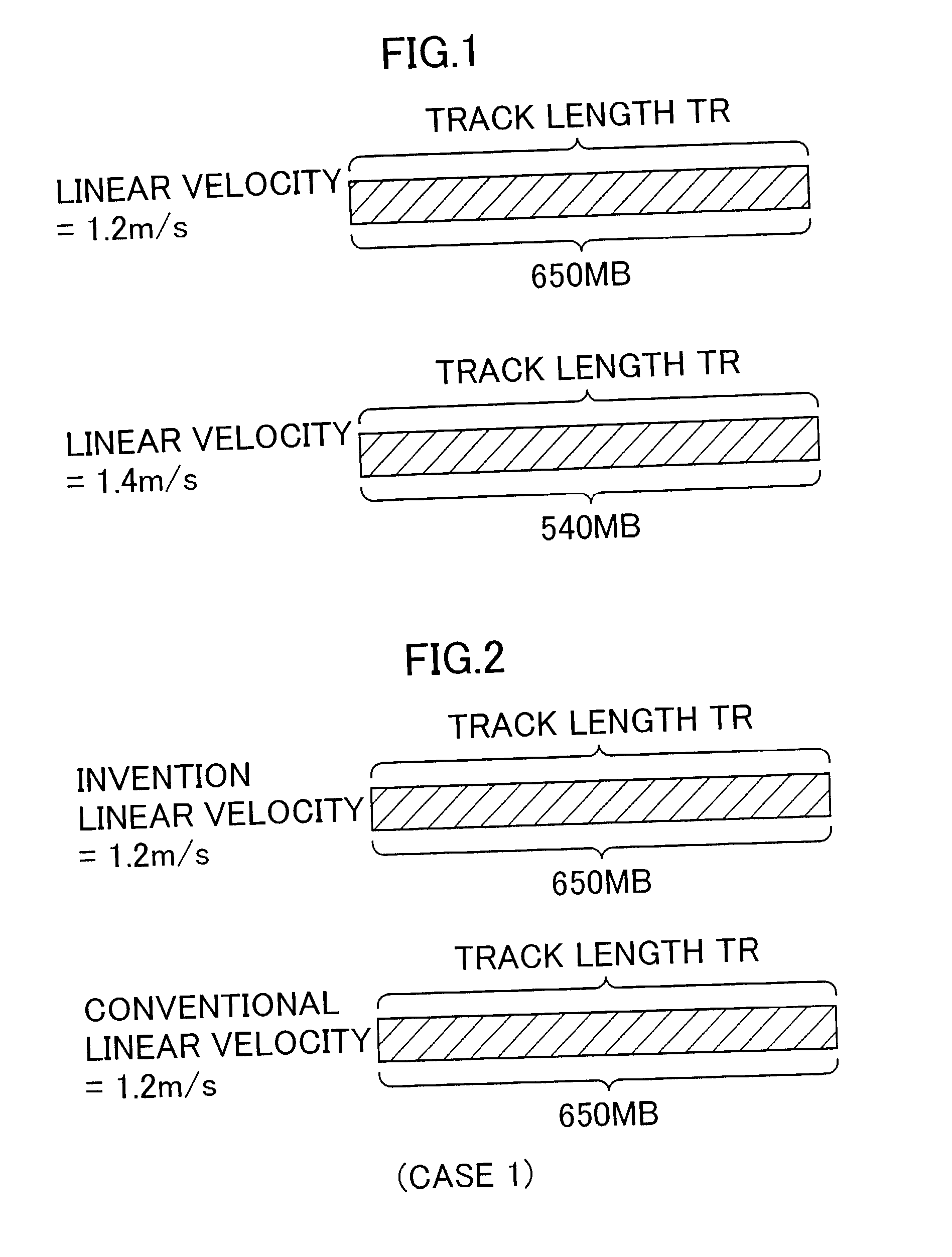
[0070] (Case 1) Recording Data Amount M=650 MB

[0071] When the recording data amount M is 650 MB, that is, when the disk capacity N meets the recording data amount M, similarly as the conventional optical disk recording apparatus, the recording is performed at the linear velocity identical to the rated linear velocity (1.2 m / s) of the CD-R as the recording object.

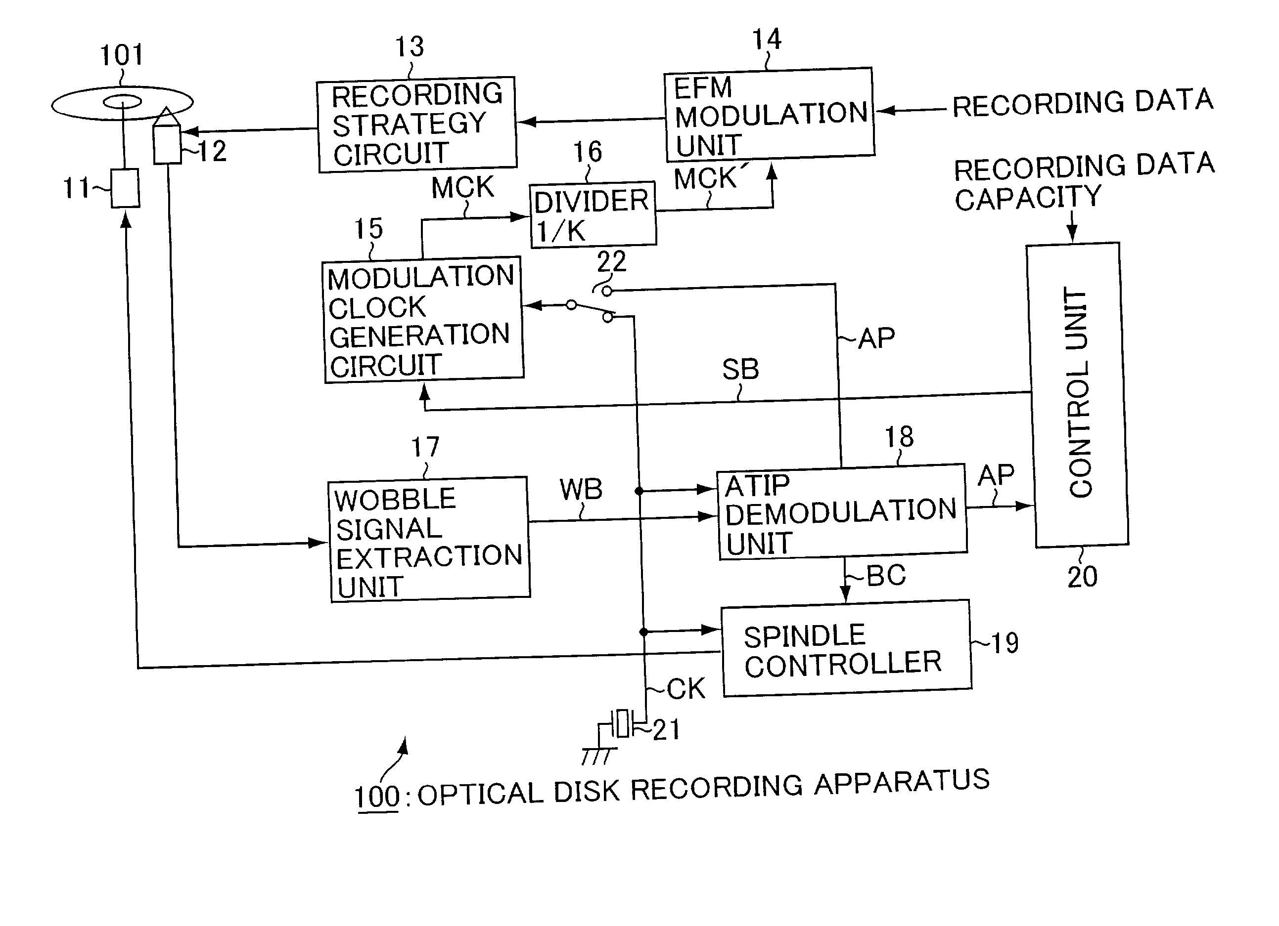
[0072] Here, the modulating clock signal MCK' and the dividing ratio of the divider 152 will be described in a case where the recording is performed with respect to the CD-R 101 (disk capacity N=650 MB) having the rated linear velocity=1.2 m / s at the rated linear velocity of 1.2 m / s with reference to FIG. 9 and FIG. 8 described above. Additionally, in the following description, the numeric values for setting the frequency and dividing ratio will be described in the case where the recording speed is set to the standard operation speed (basic speed). When the recording is performed at the multiple speeds such as the double spe...

case 2

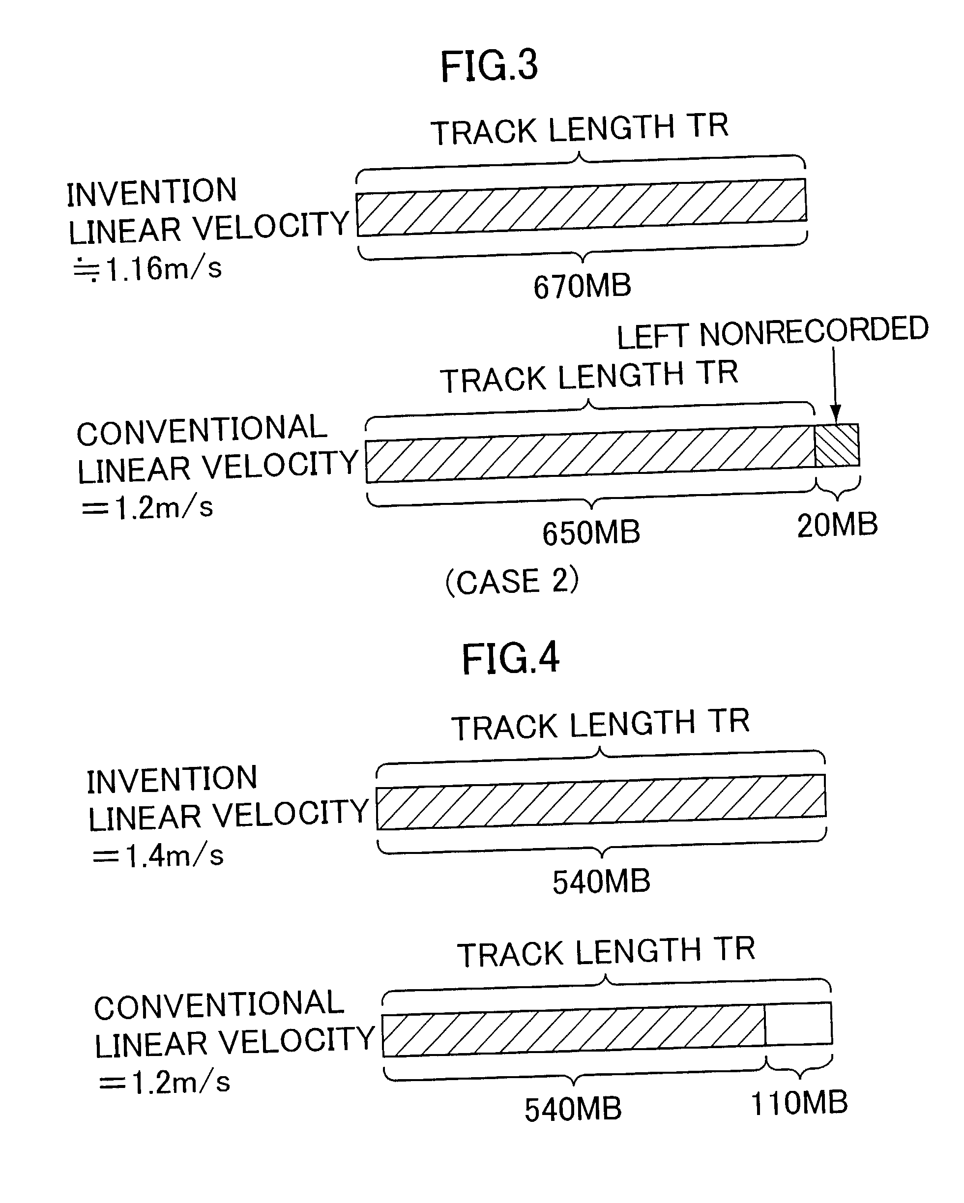
[0074] (Case 2) Recording Data Amount M=670 MB

[0075] When the recording data amount M is 670 MB, the recording information is recorded at the effective linear velocity of about 1.16 m / s as described above, and therefore the modulating clock signal MCK' supplied to the EFM modulation unit 14 has a frequency of 4.3218.times.670 / 650=4.4548 MHz. Therefore, the frequency of the modulating clock signal MCK oscillated from the voltage controlled oscillator 151 is 4.4548.times.64 (K)=285.1058 MHz. As a result, the value B for use in setting the dividing ratio of the divider 152 is 285.1058 MHz / 6.3 kHz=45255. Therefore, in Case 2, the control unit 20 outputs the control signal SB such that the dividing ratio of the divider 152 is set to 1 / 45255.

case 3

[0076] (Case 3) Recording Data Amount M=540 MB

[0077] When the recording data amount M is 540 MB, the recording is performed at the effective linear velocity of about 1.4 m / s as described above, and the modulating clock signal MCK' supplied to the EFM modulation unit 14 has a frequency of 4.3218.times.1.2 / 1.4=3.7044 MHz. Therefore, the frequency of the modulating clock signal MCK oscillated from the voltage controlled oscillator 151 is 3.7044.times.64 (K)=237.0816 MHz. As a result, the value B for use in setting the dividing ratio of the divider 152 is 237.0816 MHz / 6.3 kHz=37632. Therefore, in Case 2, the control unit 20 outputs the control signal SB such that the dividing ratio of the divider 152 is set to 1 / 37632.


PUM


Abstract

A method is designed for recording contents information along a track of an optical disk of a writeable type. A volume detection step is carried out for detecting an actual volume of the contents information to be recorded into the optical disk. A capacity detection step is carried out for detecting a nominal capacity of the optical disk, which indicates a rated volume of information to be recorded at maximum. A density determination step is carried out for determining a recording density of the contents information based on the detected actual volume and the detected nominal capacity. A record step is carried out for recording the contents information into the optical disk at the determined recording density such that the actual volume of the contents information can fit into the nominal capacity of the optical disk.

Description

[0001] 1. Technical Field of the Invention[0002] The present invention relates to an optical disk recording method and optical disk recording apparatus in which contents information is recorded in optical disks such as a compact disk-recordable (CD-R) and CD-rewritable (CD-RW).[0003] 2. Related Art[0004] In a recordable optical disk conforming to CD standard such as CD-R, a guide groove called a pregroove is formed beforehand along a track in a disk manufacturing process. The pregroove wobbles (meanders), and a wobbling frequency thereof is detected and subjected to frequency modulation (FM) with absolute time information called Absolute Time in Pregroove (ATIP).[0005] During the recording of the contents information into the optical disk in which the pregroove is formed, a wobbling signal is extracted from a photo signal of a light reflected back from the optical disk, the wobbling signal is FM-demodulated to decode ATIP information, and an absolute position along the track on the ...

Claims


Application Information

Patent Timeline
IPC IPC(8): G11B7/0037G11B7/004G11B7/0045G11B20/10G11B27/19G11B27/24G11B27/36
CPCG11B20/10G11B27/24G11B27/36G11B2020/00079G11B2220/216G11B2220/218G11B2220/2545
Inventor USUI, AKIRANAKAJO, YUKIHISA
Owner YAMAHA CORP
Why Eureka
Try Eureka