Method for optically monitoring the environment of a moving vehicle to determine an inclination angle

a technology of optical monitoring and moving vehicles, applied in the direction of instruments, television systems, image enhancement, etc., can solve the problems of erroneous decisions or inclination angle determinations, and affecting the accuracy of optical measurement results

Inactive Publication Date: 2003-01-30
CONTI TEMIC MICROELECTRONIC GMBH
View PDF2 Cites 38 Cited by
  • Summary
  • Abstract
  • Description
  • Claims
  • Application Information

AI Technical Summary

Problems solved by technology

However, the optical measurement of the spacing distance or height taken perpendicularly to the ground can be subject to substantial interferences and error-inducing variations due to unevenness of the roadway.
However, such sensors are rather expensive and complicated, and they also lead to erroneous decisions or inclination angle determ...

Method used


Image

  • Method for optically monitoring the environment of a moving vehicle to determine an inclination angle
  • Method for optically monitoring the environment of a moving vehicle to determine an inclination angle
  • Method for optically monitoring the environment of a moving vehicle to determine an inclination angle

Examples


Embodiment Construction

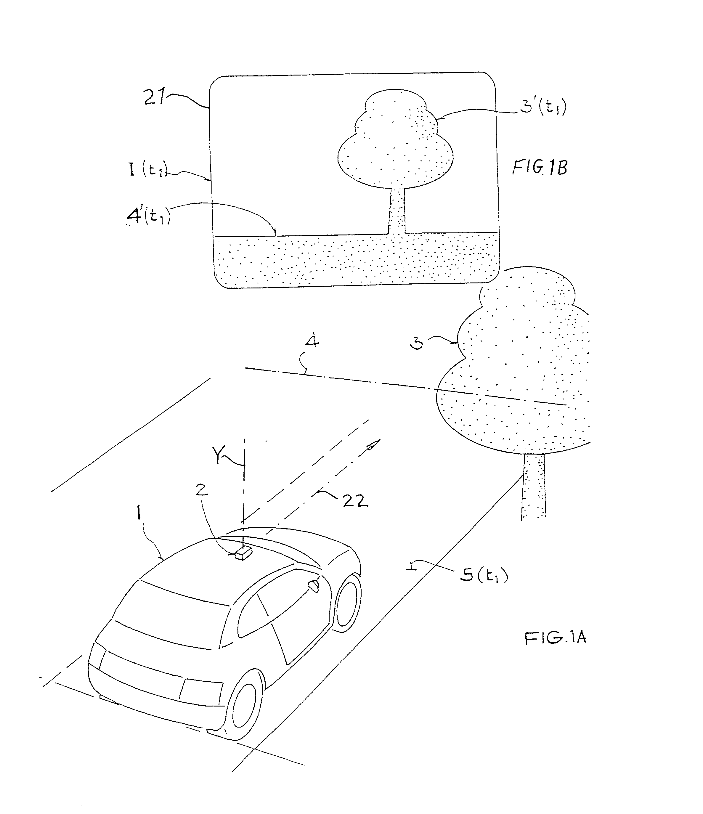
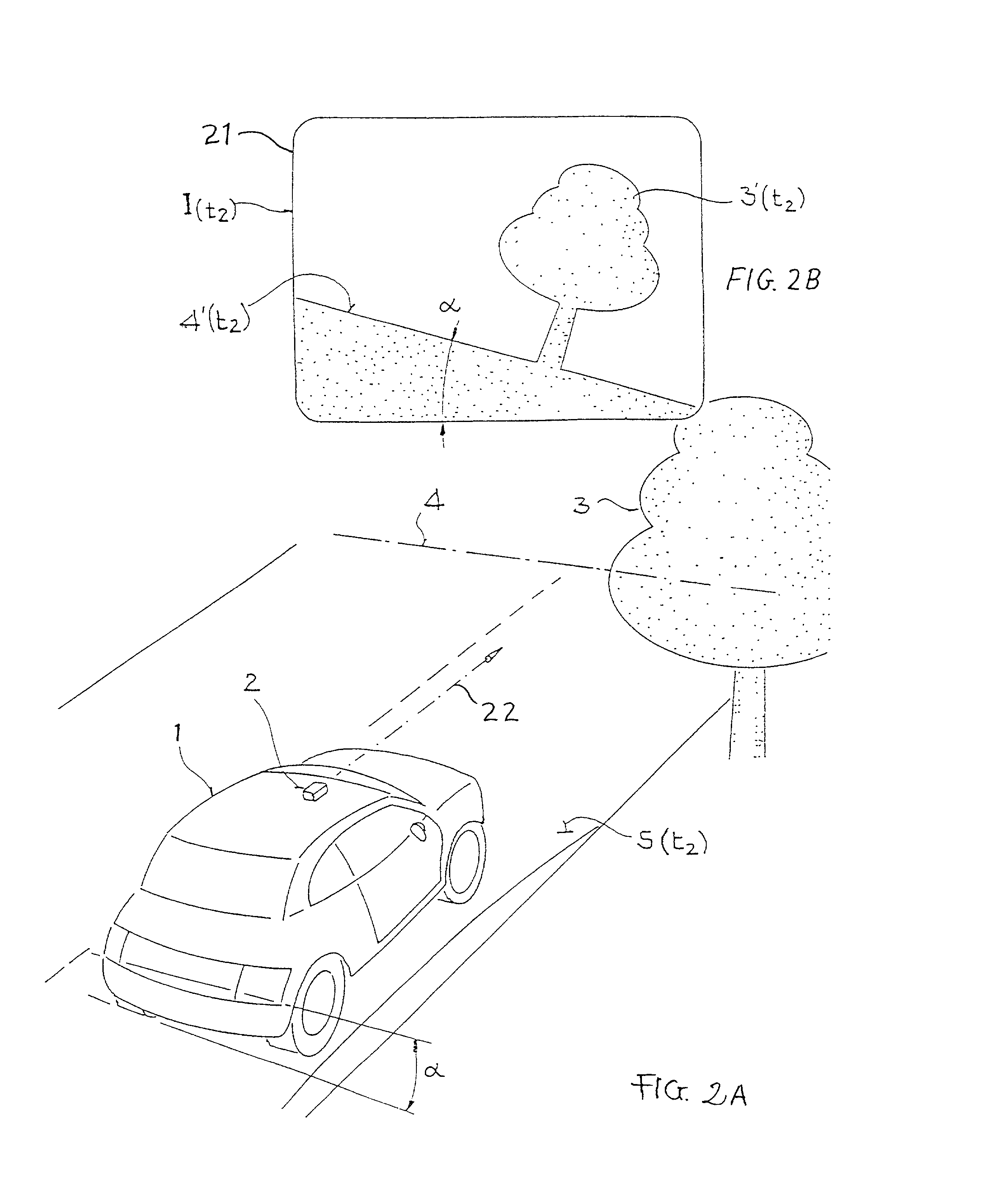
[0033] FIG. 1A schematically shows a vehicle 1 moving along a level roadway 5(t1) at a time t(1). As represented by the reference number 5(t1) of the roadway, the surface character, e.g. the inclination and the evenness thereof, varies along its length, which corresponds to a variation thereof over time with respect to the forward travel of the vehicle 1 therealong. As mentioned, at time t(1) the roadway 5(t1) is level and, particularly, horizontal.

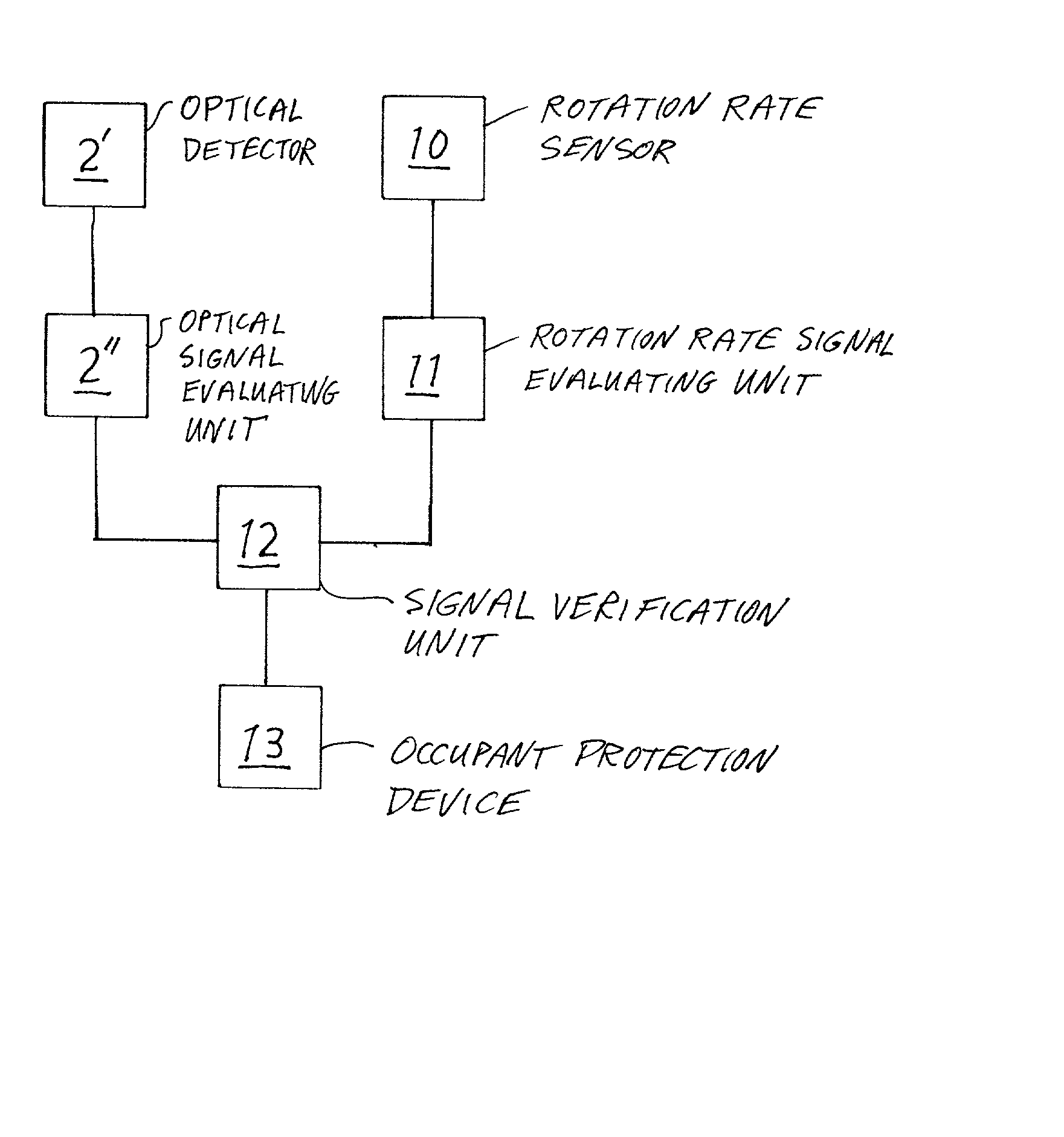
[0034] An optical unit 2, for example comprising an optical imaging device such as any conventionally known camera or optical sensor or detector, is arranged on the vehicle 1. The optical unit 2 can be arranged on or in the vehicle 1 at any selected one of various locations, arrangements, and orientations. For example, the optical unit 2 can be arranged within the vehicle 1 behind the windshield thereof, or on the roof of the vehicle 1, or at the front end thereof, for example on or in the front bumper or incorporated in the headlights th...


PUM


Abstract

The environment outside of a moving vehicle is optically monitored to acquire image information including a number of image points representing image objects or features of the outside environment. The time variation of the respective positions of the image points is analyzed to determine an inclination angle of the vehicle relative to a level horizontal plane. The optical information can be acquired by an optical camera or detector with which the vehicle has already been equipped for obstacle recognition or spacing distance control. The optically determined inclination angle is used to verify the plausibility of a rotation angle signal provided by a gyroscopic rotation rate sensor. An occupant protection device is triggered only if the two separately determined values of the inclination angle are at least approximately equal to each other and exceed a prescribed threshold.

Description

[0001] This application is a Continuation-In-Part under 35 U.S.C. .sctn.120 of our copending PCT International Application PCT / EP00 / 12087, filed on Dec. 1, 2000. The PCT International Application was published in a language other than English. The entire disclosure of the PCT International Application is incorporated herein by reference.PRIORITY CLAIM[0002] This application claims the priority under 35 U.S.C. .sctn.119 of German Patent Application 199 62 491.7, filed on Dec. 23, 1999, the entire disclosure of which is incorporated herein.[0003] The invention relates to a method for optically monitoring the surrounding environment, and of determining an inclination angle, of a vehicle moving along a roadway.BACKGROUND INFORMATION[0004] Various different methods for optically monitoring the environment surrounding a moving vehicle are already known in a variety of different applications. Such methods typically use cameras or optical detectors in order to acquire image information and ...

Claims


Application Information

Patent Timeline
IPC IPC(8): G01S17/875G01S5/16G01S17/89G01S17/931
CPCG01S5/163G01S17/875G01S17/89G01S17/936G06T2207/10016G06T2207/30244G06T2207/30252G06T7/73G01S17/931G06T7/00
Inventor LARICE, MARKUSSTEINER, WERNER
Owner CONTI TEMIC MICROELECTRONIC GMBH
Why Eureka
Try Eureka