Sensorless control system for synchronous motor
a synchronous motor and control system technology, applied in the direction of motor/generator/converter stopper, electronic commutator, dynamo-electric converter control, etc., can solve the problems of increased possibility of ringing, reduced reliability, and high-frequency oscillations
- Summary
- Abstract
- Description
- Claims
- Application Information
AI Technical Summary
Problems solved by technology
Method used
Image
Examples
embodiment 1
[0055] Embodiment 1
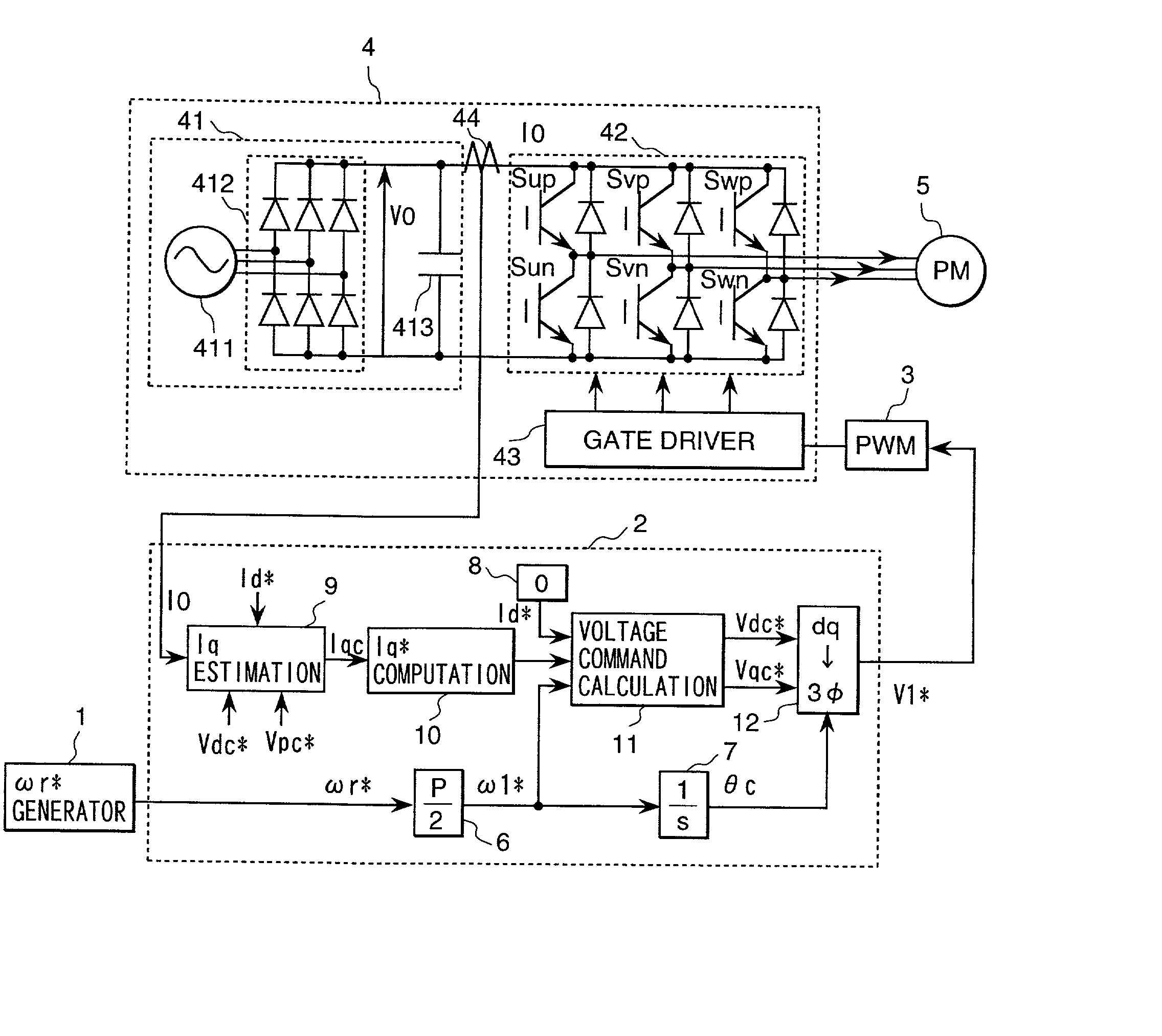
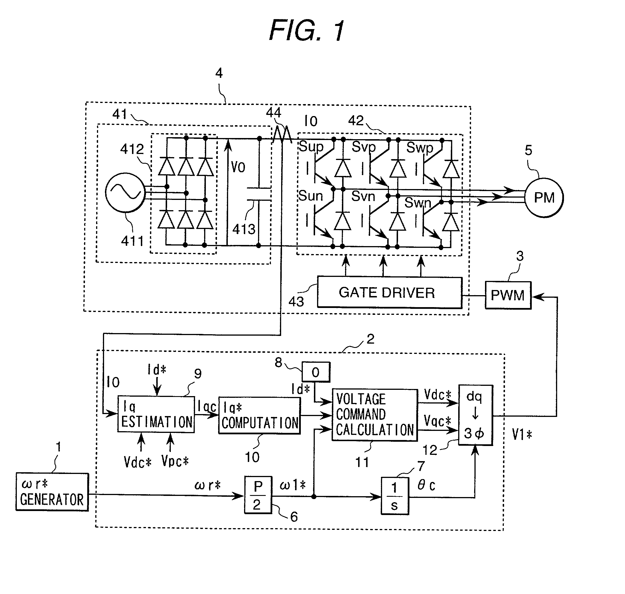
[0056] FIG. 1 is a configuration diagram of a first embodiment of the present invention. In FIG. 1, there are shown a speed command generator 1 which gives a rotational speed command .omega.r* to a motor, a controller 2 which computes the voltage applied to the motor, a PWM (pulse-width modulation) generator 3 which generates pulses to drive an inverter 4 based on a voltage command V1*, an inverter 4 which consists of semiconductor switching elements for driving the motor, a synchronous motor 5 which is a control target, a conversion gain 6 (P denotes the number of poles of the motor) which converts a rotational speed command .omega.r* to an electrical angle frequency command .omega.1* of the motor, an integrator 7 which computes an AC phase .theta.c in the controller based on the electrical angle frequency command .omega.1*, an Id* generator 8 which gives a current command Id* of the magnetic pole axis component (d-axis component) of the motor, an Iq estimator 9 ...
embodiment 2
[0073] Embodiment 2
[0074] A second embodiment of the present invention will be described in detail with reference to FIG. 5. FIG. 5 shows the configuration of a controller 2B which is used instead of the controller 2 shown in FIG. 1. Reference numerals 6 to 13 in FIG. 5 denote the same devices as represented in a first embodiment. An I0 damping gain 19 adds an adjustment value .DELTA..omega.I0 to an electrical angle frequency command .omega.1* using a detected DC current value I0 of an inverter. This embodiment adds the I0 damping gain 19 to a first embodiment.
[0075] Next, operations of a second embodiment will be explained. As shown in Equation (2), as a motor load changes and power consumption increases, a detected DC current value I0 increases if the DC voltage V0 is constant. Therefore, when the detected DC current value I0 increases, load disturbance occurs causing themotor speed to decrease. To cope with the load fluctuation without causing step-out of a motor, the speed of th...
embodiment 3
[0077] Embodiment 3
[0078] A third embodiment of the present invention will be described with reference to FIG. 6. FIG. 6 shows the configuration of a controller 2C which is used instead of the controller 2 shown in a first embodiment. Reference numerals 6 to 13 in FIG. 6 denote the same devices as represented in a first embodiment. An Iq damping gain 20 adds an adjustment value .DELTA..omega.q to an electrical angle frequency command .omega.1* using the estimated torque current value Iqc. This embodiment adds the Iq damping gain 20 to a first embodiment.
[0079] Next, operations of a third embodiment will be described. A second embodiment uses a detected DC current value I0 to correct an electrical angle frequency command .omega.1*, while this embodiment uses an estimated torque current value Iqc to correct the electrical angle frequency command .omega.1*. The detected DC current value I0 is a physical quantity which fluctuates in response to power consumption of a motor, however, the...
PUM
 Abstract
Description
Claims
Application Information
 - R&D
- Intellectual Property
- Life Sciences
- Materials
- Tech Scout
- Unparalleled Data Quality
- Higher Quality Content
- 60% Fewer Hallucinations
Browse by: Latest US Patents, China's latest patents, Technical Efficacy Thesaurus, Application Domain, Technology Topic, Popular Technical Reports.
© 2025 PatSnap. All rights reserved.Legal|Privacy policy|Modern Slavery Act Transparency Statement|Sitemap|About US| Contact US: help@patsnap.com


