Resonant antennas

Inactive Publication Date: 2003-02-20
LUCENT TECH INC
View PDF0 Cites 29 Cited by
  • Summary
  • Abstract
  • Description
  • Claims
  • Application Information

AI Technical Summary

Benefits of technology

0007] Various embodiments use antennas that resonantly couple to external radiation at communication frequencies. Due to the resonant couplin

Problems solved by technology

Nevertheless, antennas whose linear dimensions are of order of the radiation wavelength are not practical in many situations.
In particular, cellular telephones and handheld wireless devices are small

Method used


Image

  • Resonant antennas
  • Resonant antennas
  • Resonant antennas

Examples


Example

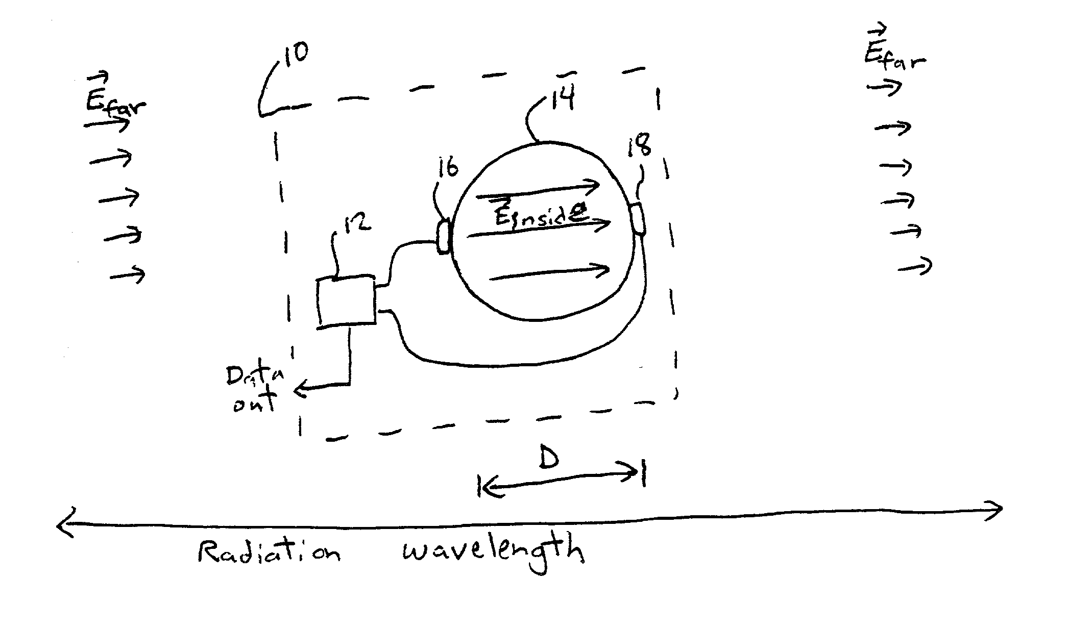
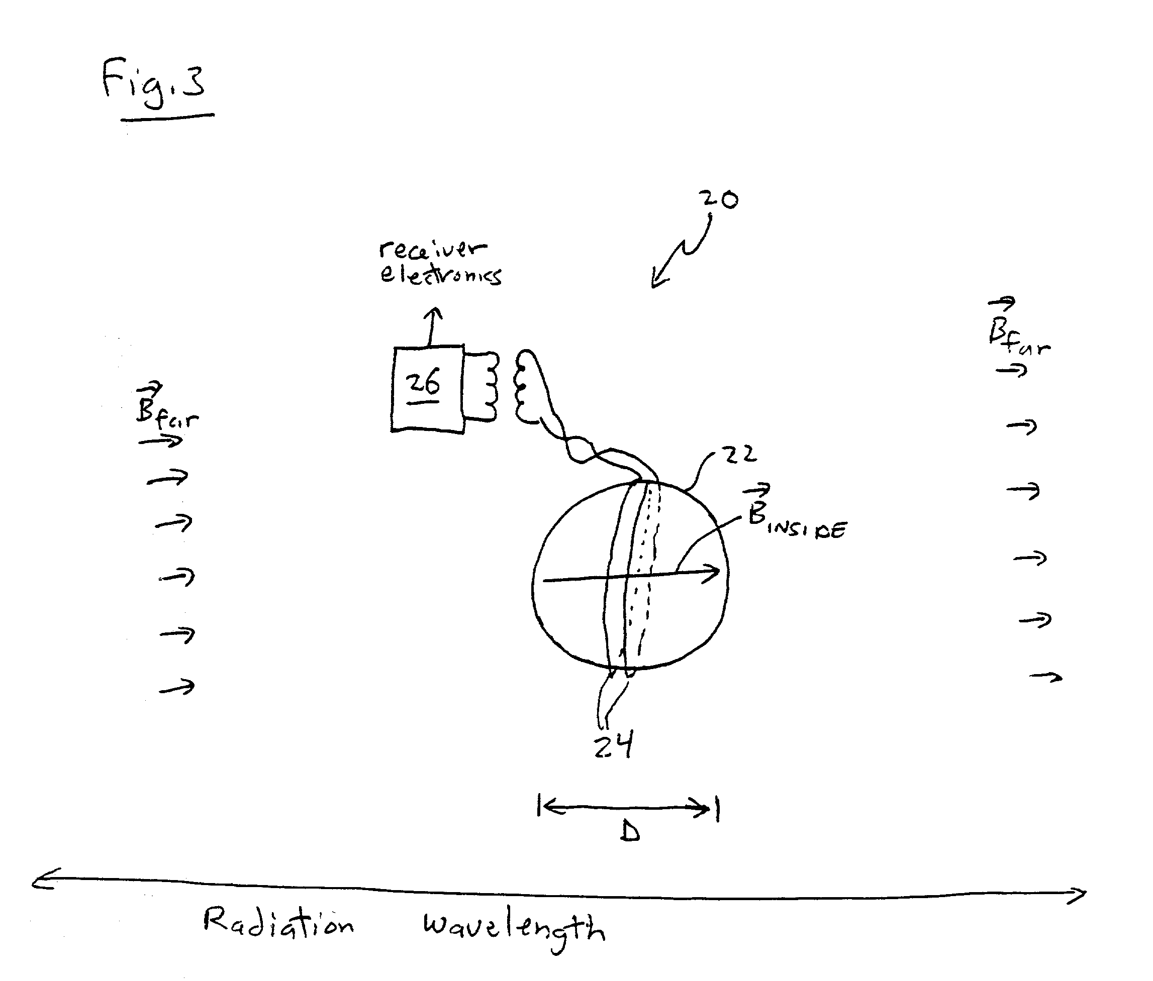
[0014] Various embodiments include antennas fabricated of manmade metamaterials for which the dielectric constant (.epsilon.) and / or magnetic permeability (.mu.) is negative over a range of microwave frequencies. The metamaterials are selected to cause the antennas to couple resonantly to external radiation having communication frequencies. Due to the resonant couplings, the antennas have a high sensitivity to the radiation even though their linear dimensions are much smaller than the wavelength of the radiation.

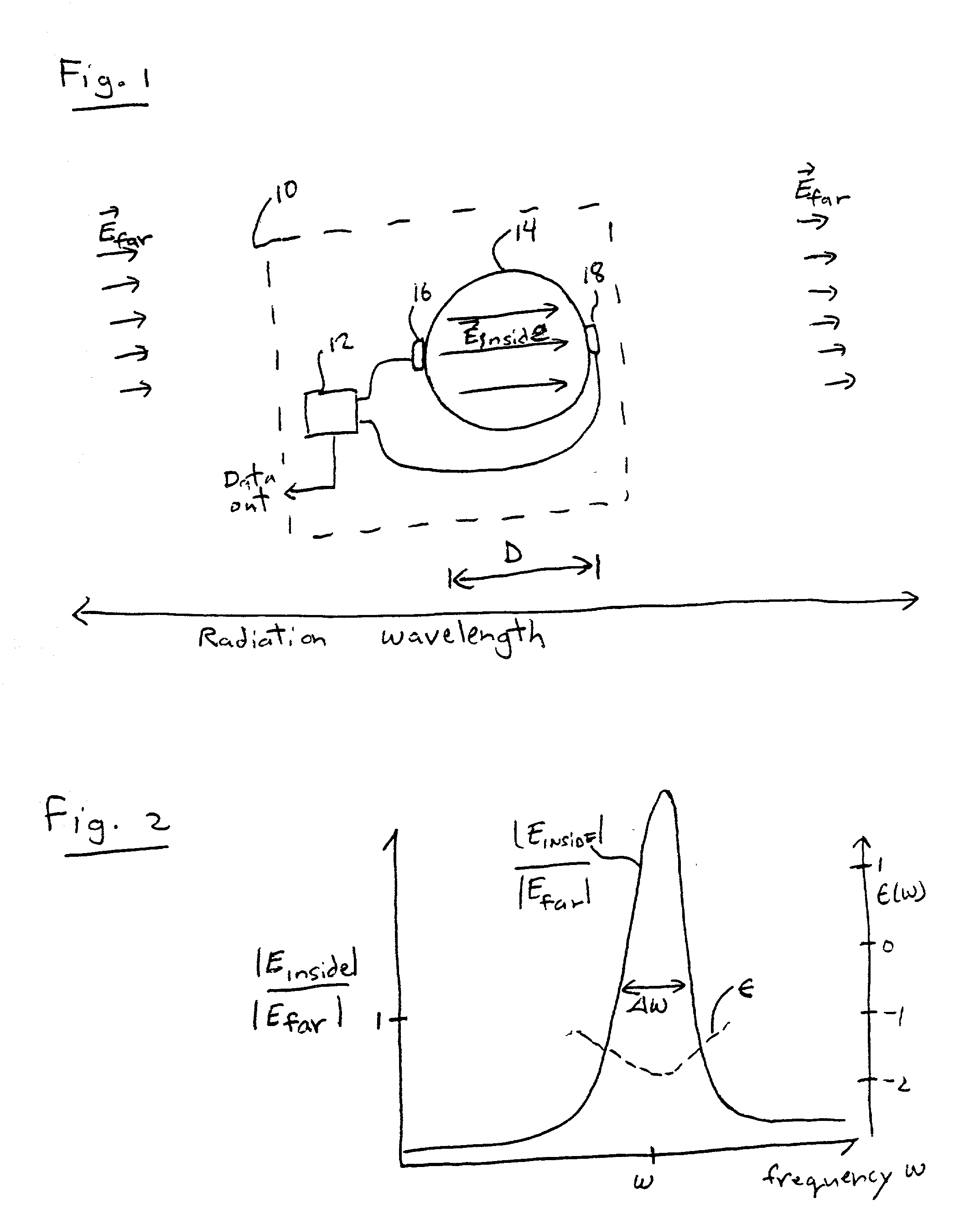
[0015] The resonant coupling results from selecting the metamaterial to have appropriate .epsilon. and / or .mu. values. An appropriate selection of the metamaterial depends on the shape of the object and the frequency range over which a resonant response is desired. For spherical antennas .epsilon. and / or .mu. must have real parts approximately equal to "-2" in the frequency range, i.e., at communication frequencies. For such values of .epsilon. and / or .mu., a spherical anten...


PUM


Abstract

An apparatus includes an object and one or more sensors located adjacent to or in the object. The object is formed of a material whose dielectric constant or magnetic permeability has a negative real part at microwave-frequencies. The one or more sensors are located adjacent to or in the object and measure an intensity of an electric or a magnetic field therein.

Description

[0001] This application claims the benefit of U.S. Provisional Patent Application No. 60 / 313,310, filed Aug. 18, 2001.BACKGROUND OF THE INVENTION[0002] 1. Field of the Invention[0003] The inventions relate to antennas and microwave transceivers.[0004] 2. Description of the Related Art[0005] Conventional antennas often have linear dimensions that are of order of the wavelength of the radiation being received and / or transmitted. As an example a typical radio transmitter uses a dipole antenna whose length is about equal to 1 / 2 of the wavelength of the waves being transmitted. Such an antenna length provides for efficient coupling between the antenna's electrical driver and the radiation field.[0006] Nevertheless, antennas whose linear dimensions are of order of the radiation wavelength are not practical in many situations. In particular, cellular telephones and handheld wireless devices are small. Such devices provide limited space for antennas. On the other hand, small antennas couple...

Claims


Application Information

Patent Timeline
IPC IPC(8): G01R33/02G01R27/28G01R29/08H01Q1/38H01Q1/40H01Q5/10H01Q7/06H01Q9/04H01Q13/28H01Q15/08H04B1/18
CPCH01Q9/0485H01Q15/08H01Q13/28
Inventor ISAACS, ERIC D.PLATZMAN, PHILIP MOSSSHEN, JUNG-TSUNG
Owner LUCENT TECH INC
Why Eureka
Try Eureka