Phase-change optical information recording medium, and optical information recording and reproducing apparatus and method for the same

a technology of optical information and recording medium, which is applied in the direction of optical recording/reproducing/erasing methods, record information storage, instruments, etc., can solve the problems of high noise level in the low power region, particularly becoming eviden

Inactive Publication Date: 2003-02-20
RICOH KK +1
View PDF2 Cites 27 Cited by
  • Summary
  • Abstract
  • Description
  • Claims
  • Application Information

AI Technical Summary

Problems solved by technology

However, when conducting recording and reproducing operations on a phase-change optical information recording medium with a blue LD, the noise level is high in the low power region, and it particularly becomes evident during reproducing operation.

Method used


Image

  • Phase-change optical information recording medium, and optical information recording and reproducing apparatus and method for the same
  • Phase-change optical information recording medium, and optical information recording and reproducing apparatus and method for the same
  • Phase-change optical information recording medium, and optical information recording and reproducing apparatus and method for the same

Examples


example 1

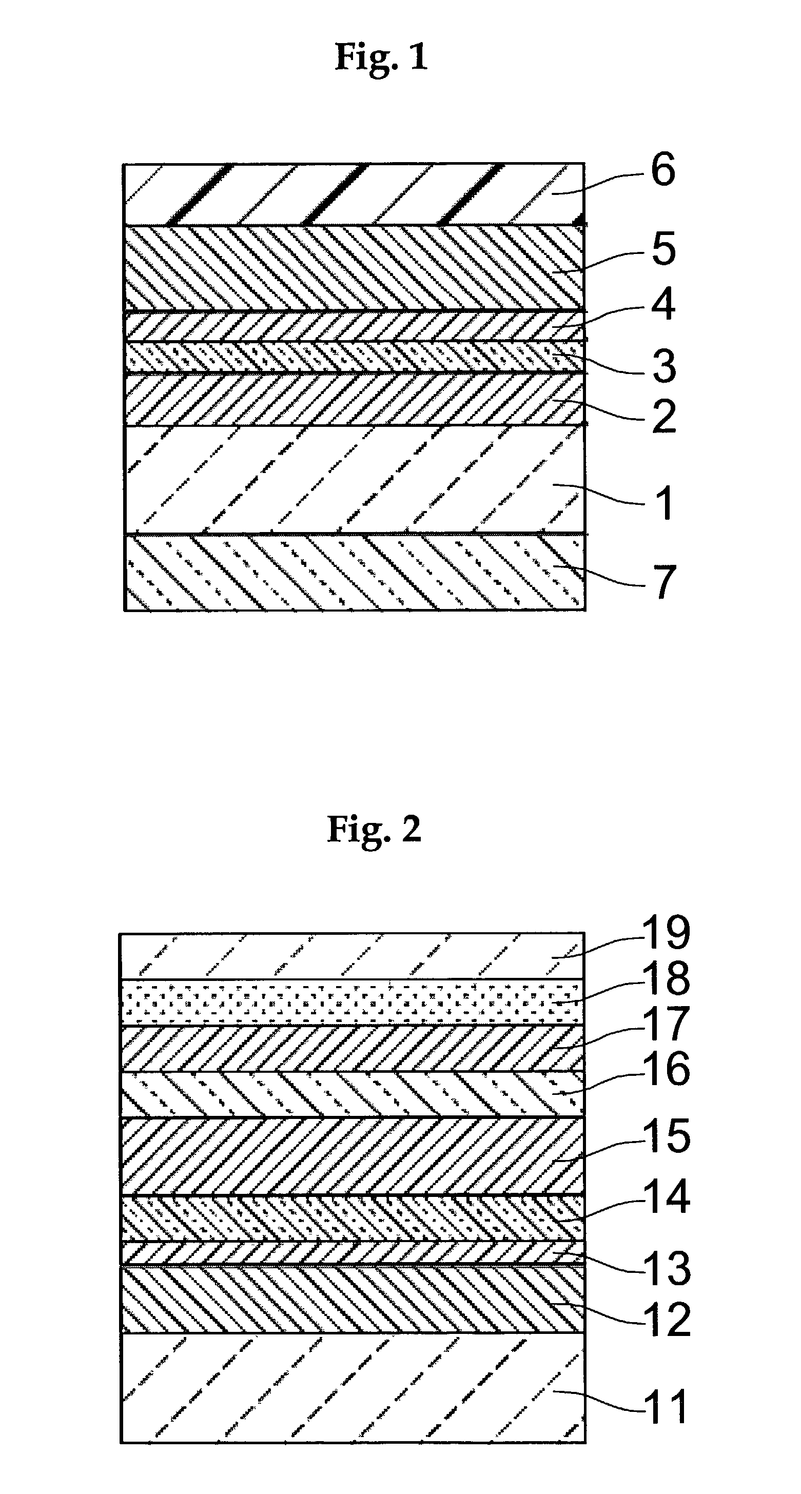
[0044] On a disk-shaped polycarbonate substrate having a track pitch of 0.35 .mu.m, a thickness of 1.1 mm and a diameter of 120 mm, a first protective layer (ZnS--SiO.sub.2) having a thickness of 40 nm, a recording layer (Sb.sub.68Te.sub.29Ge.sub.3) having a thickness of 12 nm, a second protective layer (ZnS--SiO.sub.2) having a thickness of 14 nm, and a heat-resistant layer (AgPdCu) having a thickness of 120 nm were formed in this order by a sheet fed spatter device. On the obtained structure, radical UV resin (MH7617N, produced by Mitsubishi Rayon Co., Ltd.) was thickened to 5 .mu.m as well as forming a light transmittance thermally controllable layer (Sb.sub.2O.sub.3) to a 30 nm-thick at a side of the disk where a light beam transmits. Thus, a phase-change optical disk having a final thickness of 1.2 mm according to the present invention was formed as shown in FIG. 1.

examples 2-4

[0054] Phase-change optical disks according to the present invention were prepared following the same procedure as in Example 1, except for using material described in Table 1 as the light transmittance thermally controllable layer. The recording layers of the prepared phase-change optical disks were initialized and examined for their reproducing qualities as in Example 1. The results are shown in Table 1.

examples 5-8

[0055] On a disk-shaped polycarbonate substrate having a track pitch of 0.35 .mu.m, a thickness of 1.1 mm and a diameter of 120 mm, a heat-resistant layer (Ag.sub.94Cu.sub.3Pd.sub.3) having a thickness of 100 nm, a third protective layer (ZnS--SiO.sub.2) having a thickness of 3 nm, a light transmittance thermally controllable layer (Table 1), a second protective layer (ZnS--SiO.sub.2) having a thickness of 5 nm, a recording layer (Ag.sub.5In.sub.5Sb.sub.65Te.sub.25) having a thickness of 10 nm, and a first protective layer (ZnS--SiO.sub.2) having a thickness of 100 nm were formed in this order by a sheet fed spatter machine. On the obtained structure, a thin substrate of polycarbonate having a thickness of 0.6 mm was attached by means of an acrylic adhesive (DA8310-A50, produced by Nitto Denko Corporation). Thus, a phase-change optical disk having a final thickness of 1.2 mm according to the present invention was formed as shown in FIG. 2.

[0056] For crystallization of a recording la...


PUM

PropertyMeasurementUnit
recording wavelengthaaaaaaaaaa
refractive indexaaaaaaaaaa
thicknessaaaaaaaaaa

Abstract

The present invention relates to a phase-change optical information recording medium comprising a recording layer which reversibly phase-changes between the crystalline phase and the amorphous phase by irradiation of a light having a recording wavelength of 390 to 430 nm, and a light transmittance thermally controllable layer showing a light transmittance varying according to temperature, in which the light transmittance increases at a rate of 0.2 to 0.7% /10° C.

Description

[0001] 1. Field of the Invention[0002] The present invention relates to a phase-change optical information recording medium in which information may be recorded and reproduced by irradiating a beam to a recording layer to generate optical change of material of the recording layer, thereby simultaneously rewriting the information, and an optical information recording and reproducing apparatus and method for the same.[0003] 2. Description of the Related Art[0004] In conventional optical information recording and reproducing apparatuses using phase-change optical information recording media, a wavelength-dependent filter has been used to obtain a beam having a wavelength suitable for recording and reproducing operation. Exmaples of the wavelength-dependent filter include quarter wavelength plate and a filter using liquid crystals to change a numerical aperture.[0005] Japanese Patent Application Laid-Open (JP-A) No. 05-234136 discloses a better technique to reproduce optical information...

Claims


Application Information

Patent Timeline
Patent Type & Authority Applications(United States)
IPC IPC(8): G11B7/0045G11B7/005G11B7/135G11B7/24G11B7/243G11B7/257
CPCG11B7/0045G11B7/005G11B7/24G11B7/243G11B7/257G11B2007/25706G11B2007/2571G11B2007/25713G11B2007/25715
Inventor SHINOTSUKA, MICHIAKIIWASA, HIROYUKIYAMADA, TAKAOMATSUSHITA, TOSHIOKANBARA, YASUOOKAUCHI, SHIGEKI
Owner RICOH KK
Why Eureka
Try Eureka