
Device for determining at least one parameter of a flowing medium

a technology of at least one parameter and a flow medium, applied in liquid/fluent solid measurement, instruments, machines/engines, etc., can solve the problems of invalidating the measurement, high degree of sophistication, heat dissipation of the measuring resistor,

Inactive Publication Date: 2003-02-27
ROBERT BOSCH GMBH
View PDF3 Cites 16 Cited by
  • Summary
  • Abstract
  • Description
  • Claims
  • Application Information

AI Technical Summary

Benefits of technology

[0013] It is advantageous to secure the sensor carrier in a bypass channel or in a support part, since this simplifies the assembly.
[0015] For optimized circumflow of the sensor element, it is advantageous if the sensor element is installed flush with respect to a top surface of the sensor carrier, and / or if a small gap is present between the sensor element and the sensor cavity.
[0017] During assembly, it is advantageous that an adhesive bead, which completely seals the sensor region of the sensor element in the sensor cavity, is placed into the cut-outs in the longitudinal edges of the sensor cavity, transversely over the bottom of the sensor cavity, and that depressions are applied in the edge area of the sensor cavity bottom, so that the sensor element can be mounted more exactly. This adhesive bead prevents soiling of the sensor element by reliably stopping the gel which protects an evaluation circuit from moisture.
[0019] Moreover, it is advantageous to use plastic or ceramic, since plastic does not corrode so seriously compared to metal, and therefore no further corrosion protection is necessary.
[0020] Since it is advantageously possible to place the sensor element very precisely in the sensor cavity due to the narrowing of the tolerances because of the use of plastic, there is no longer any flow below the sensor element.

Problems solved by technology

It is extremely important that the sensor element be glued in position in the recess with its top surface as flush as possible with respect to the top surface of the sensor carrier, since just the smallest displacement, e.g. because of an unevenly applied adhesive layer, results in eddies and flow separation regions which, particularly at the surface of the sensor element, disadvantageously influence the heat dissipation of the measuring resistor and invalidate the measuring result.
Therefore, very small mass tolerances must be provided for the recess, and the most extreme care is necessary when gluing the sensor element into the recess of the sensor carrier, so that particularly when the device is mass-produced, a high degree of sophistication is necessary from a standpoint of production engineering, resulting in considerable production costs.
The various work steps for producing the frame and retaining elements are disadvantageous.
However, this is not disadvantageous, since this effect can be suppressed by zero-point measuring and calibration; although, during the service life of the sensor element, the measuring result is invalidated if this folding gap is obstructed by dirt and / or liquid particles, and the calibration is no longer correct.
It is disadvantageous that the spacers are first formed by a further shaping process.
It is also disadvantageous that, because of the flowing corrosive medium, a corrosion-protection layer such as NiNiP must be applied on the sensor carrier by an additional costly electroplating process or a coating method which further increases the dimensional tolerances and the production times and costs.
When working with such a self-supporting way of mounting the sensor element, because of tolerances during production, a gap develops between the sensor element and the recess of the sensor carrier.
The gap can be so large that in the case of the sensor element, an unwanted flow in the hollow space below its membrane in the recess may come about, which has a disadvantageous effect on the measuring result of the device.
Disadvantageous in both methods is that only by the special arrangement of gluing seams or by additional measures is the flow diverted around the hollow space in order to compensate for the effects of the manufacturing tolerances.
In this connection, the disadvantages from the standpoint of production engineering result, that gaps must additionally be created, the flow of the gel not being stopped, but rather only being diverted in a defined manner.

Method used


Image

  • Device for determining at least one parameter of a flowing medium
  • Device for determining at least one parameter of a flowing medium
  • Device for determining at least one parameter of a flowing medium

Examples


Embodiment Construction

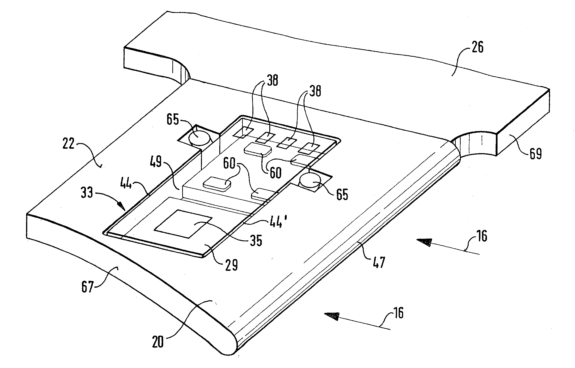
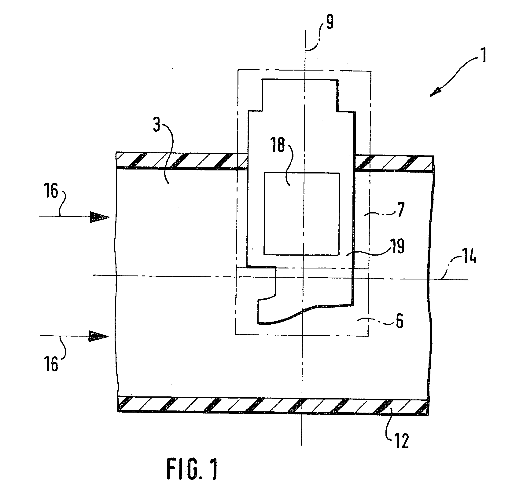
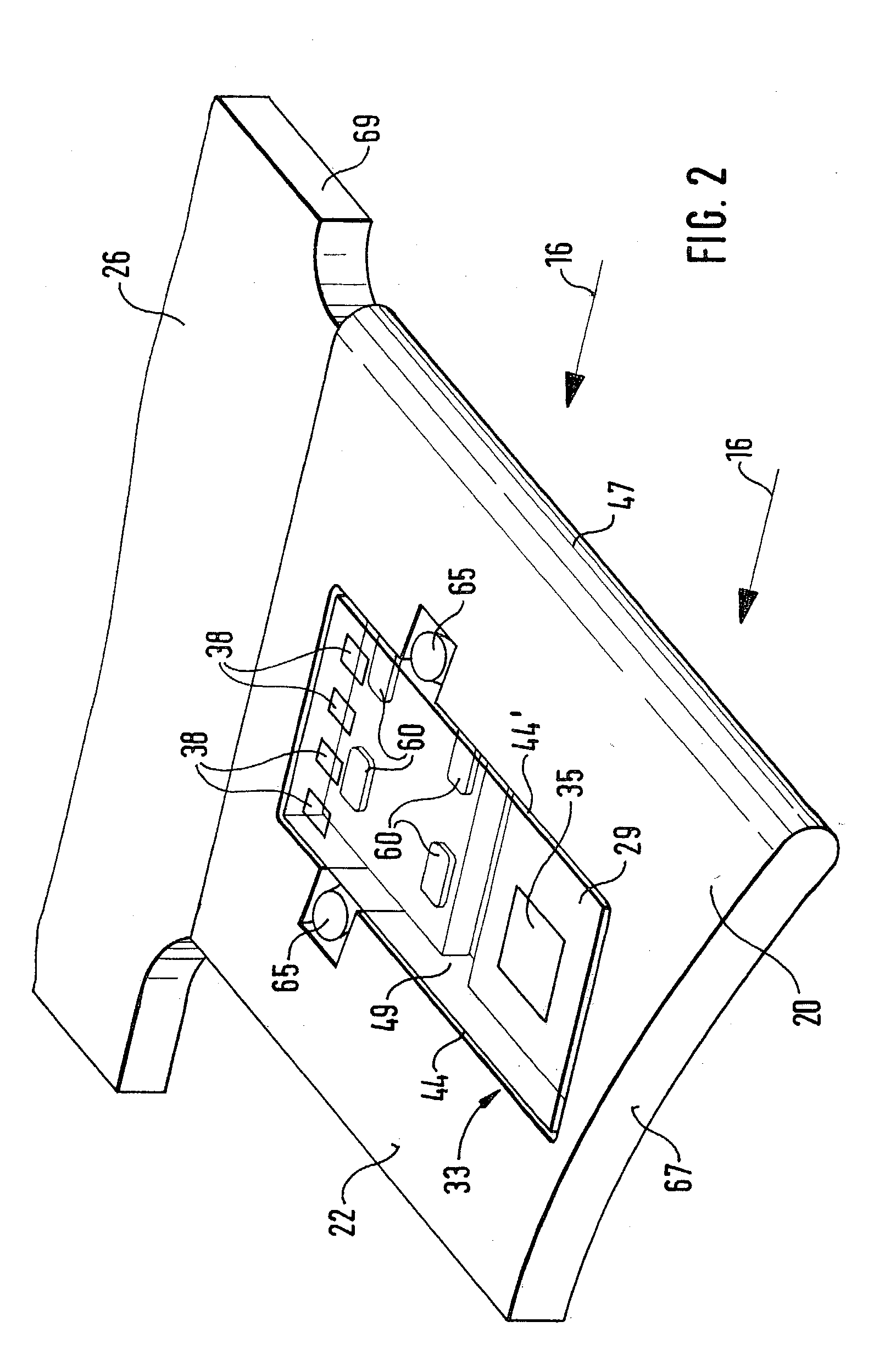
[0030] FIG. 1 shows schematically how a device 1 is installed in a line 3 in which a medium to be measured is flowing. Device 1 is used for determining at least one parameter of the flowing medium and is made of a measuring housing 6, denoted by a lower rectangle indicated by a dot-dash line, and a support part 7, denoted by an upper rectangle indicated by a dot-dash line, in which, for example, an evaluation electronics 18 is accommodated, for instance, on a base support 26 (FIG. 2) in an electronics space 19. Parameters of a flowing medium are, for example, the volumetric air flow for ascertaining an air mass, a temperature, a pressure, a concentration of a component in the medium or a flow velocity, which are determined by suitable sensors. It is possible to use device 1 for determining further parameters. Parameters may be determined using one or more sensors, one sensor also being able to determine two or more parameters. Measuring housing 6 and support part 7 have a common lon...


PUM


Abstract

The present invention relates to a device having a sensor carrier, on which is arranged a sensor element introduced into the flowing medium. According to the related art, the sensor carrier made of metal is mounted on a component of the device. For the installation of the measuring element, the component must be present with the sensor carrier. The sensor carrier (20) of the present invention is produced separately, and the at least one sensor element (33) may be inserted immediately into the sensor carrier (20). For example, the sensor carrier (20) is mounted on a component of the device (1) by adhesive.

Description

BACKGROUND INFORMATION[0001] The present invention is based on a device for determining at least one parameter of a medium flowing in a line, having a sensor carrier for accommodating a sensor element, according to the species defined in claim 1.[0002] The German Patent 44 26 102 C1 and the U.S. Pat. No. 5,693,879 describe a sensor carrier for a sensor element in an air-mass measuring device, the sensor carrier extending with the sensor element into a measuring channel in which a medium is flowing. The sensor element supplies a measuring signal used for calculating the mass of the flowing medium. The sensor carrier has a recess in which the sensor element is flush-mounted and retained by an adhesive layer applied on a bottom surface of the recess. In this case, the sensor carrier is produced in that first of all, an opening which corresponds approximately to the outer shape of the sensor element is made in a metal strip; the metal strip is thereupon bent about a bending axis outside...

Claims


Application Information

Patent Timeline
IPC IPC(8): F02D35/00G01F1/684
CPCG01F1/6842G01F1/6845G01K13/02F02D35/00
Inventor ROECKEL, HERBERTRENNINGER, ERHARDHECHT, HANSHUEFTLE, GERHARDSTROHRMANN, MANFREDSCHARD, RAINERWANJA, ROLAND
Owner ROBERT BOSCH GMBH
Learn More