Severing machine for articles of weblike material having a sharpening zone for the blades sepatate from the cutting zone

a cutting machine and web-like material technology, applied in the field of cutting machines, can solve the problems of high risk and fire risk, and achieve the effect of reducing the contamination of the cutting articl

a cutting machine and web-like material technology, applied in the field of cutting machines, can solve the problems of high risk and fire risk, and achieve the effect of reducing the contamination of the cutting articl

US20030037653A1Inactive Publication Date: 2003-02-27FABIO PERINI SPA

Image

  • Severing machine for articles of weblike material having a sharpening zone for the blades sepatate from the cutting zone
  • Severing machine for articles of weblike material having a sharpening zone for the blades sepatate from the cutting zone
  • Severing machine for articles of weblike material having a sharpening zone for the blades sepatate from the cutting zone

Examples


Embodiment Construction

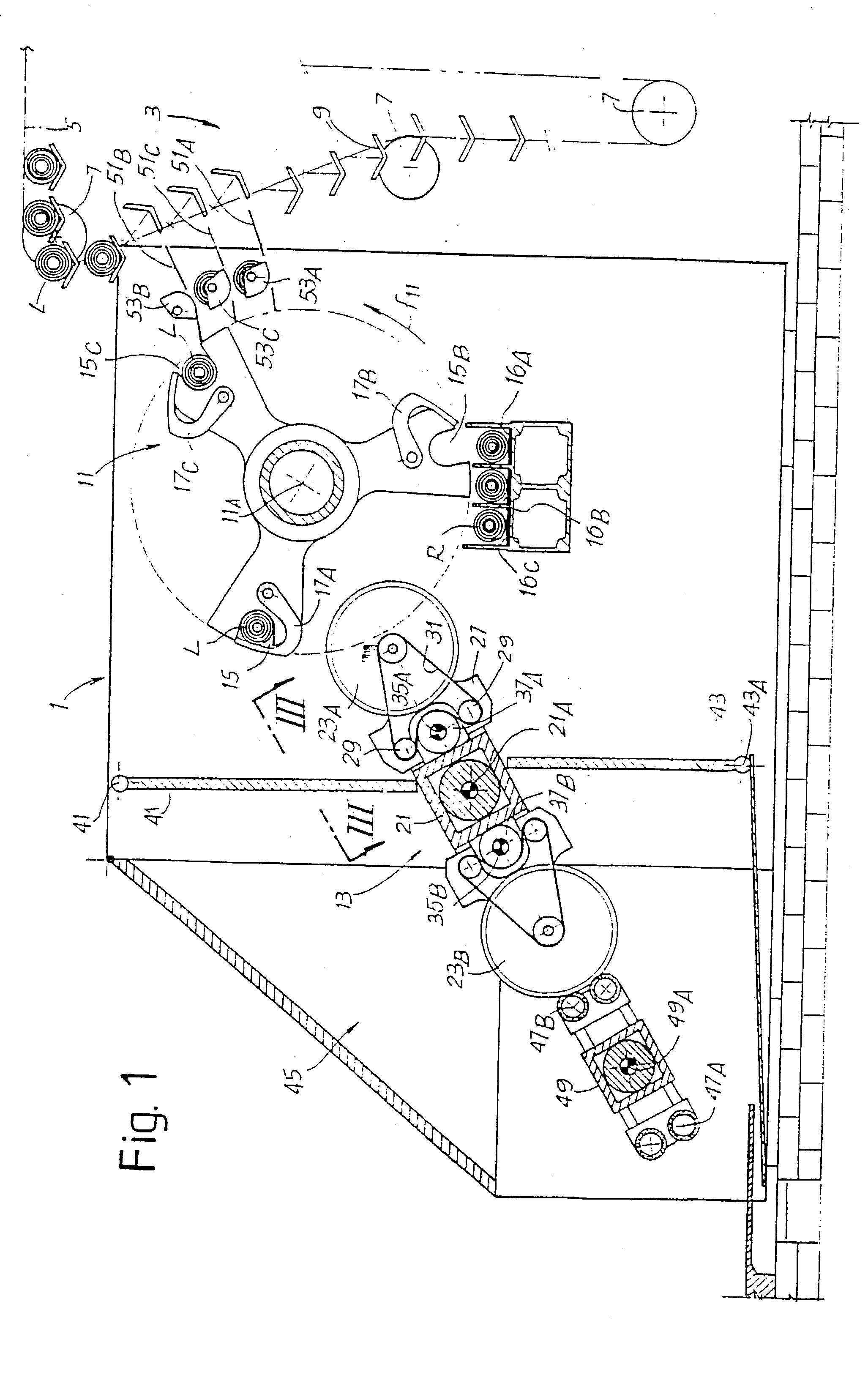
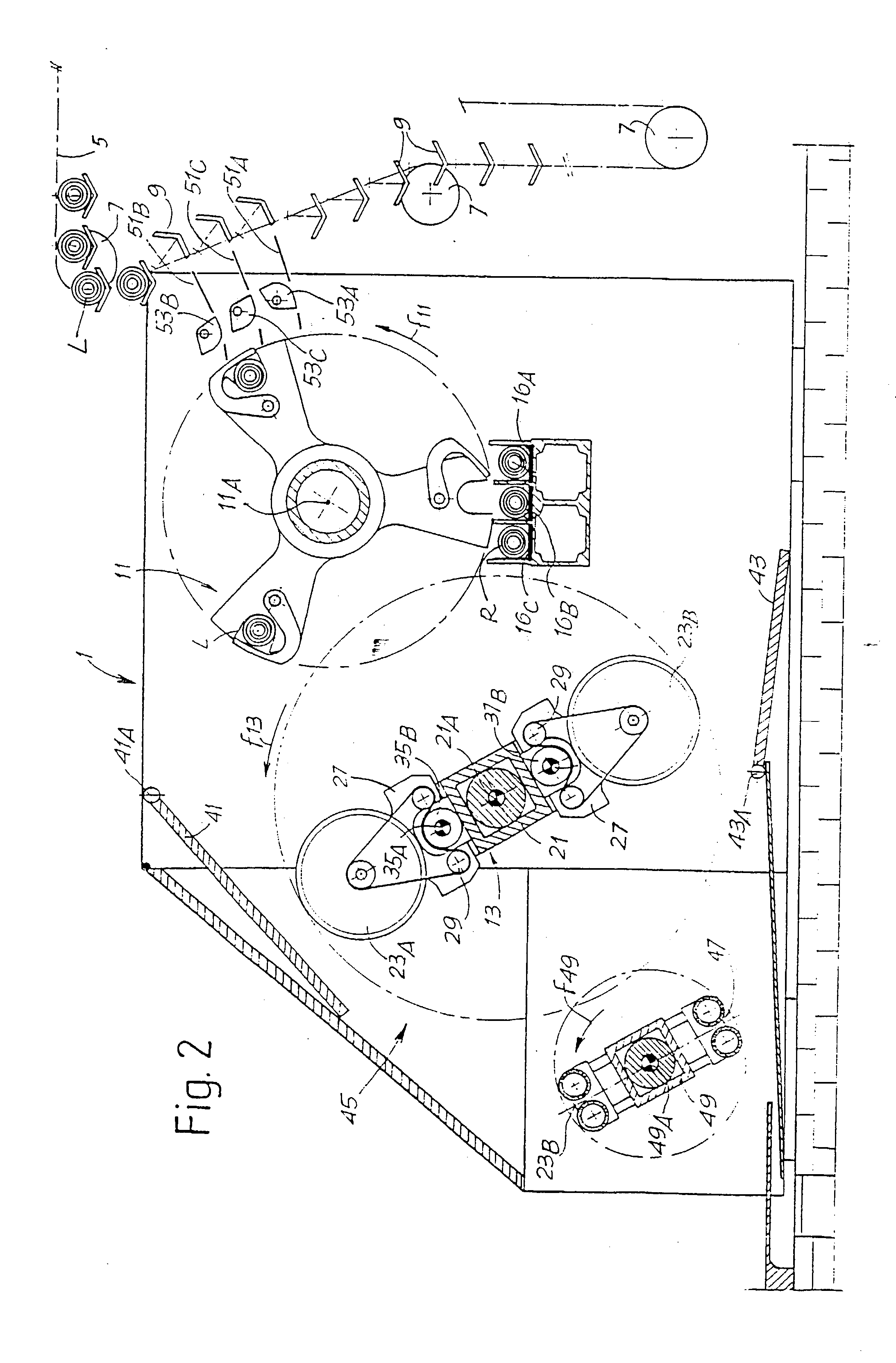
[0026] The severing machine, generally designated 1, is fed with series of rolls or logs L by a storage unit 3 arranged on one side of the machine. The storage unit 3 comprises a flexible member 5 passed around a series of pulleys 7 and bears a plurality of oscillating cradles 9, which unload the logs L to loading positions in the severing machine, in a manner that will be described below. The storage unit 3 is of a type known per se and will not be described in more detail. It may be replaced by any other system for feeding the logs to be cut.

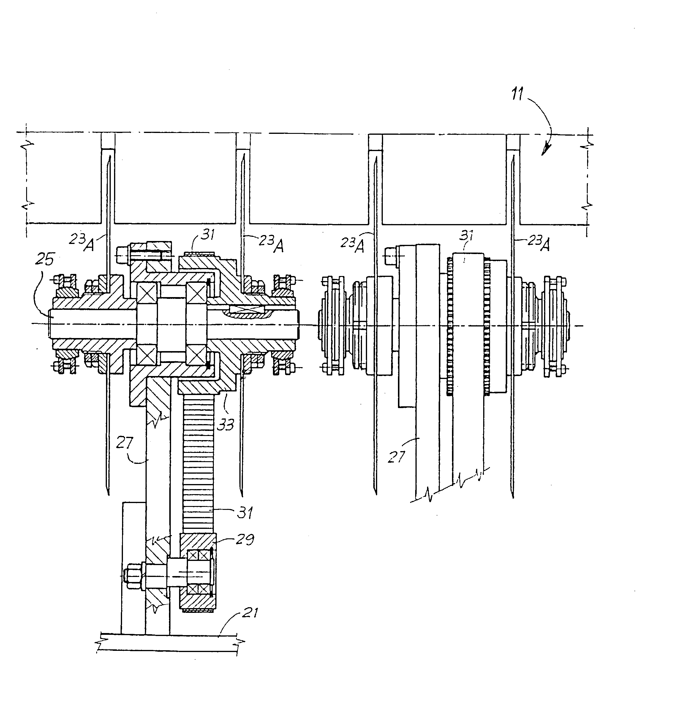
[0027] The severing machine 1 has a rotating feeder 11 which takes the incoming rolls L and presents them to a cutting unit 13. In the example shown, the rotating feeder 11 is constituted by an assembly rotating about a horizontal shaft 11A and is equipped with three seatings 15A, 15B and 15C, arranged at steps of 120.degree. relative to one another about the axis of rotation 11A. Associated with each seating 15A, 15B, 15C is a respective reta...


PUM

PropertyMeasurementUnit
rotationaaaaaaaaaa
flexibleaaaaaaaaaa
lengthaaaaaaaaaa

Abstract

The severing machine comprises at least a first series of disk-shaped blades (23A; 23B) rotating about their own axis, which series is carried by a moveable support (21) capable of bringing the series of blades alternately into an active zone wherein the cutting of the products takes place and a parking zone. In addition, at least one barrier (41, 43) is provided separating the active zone from the parking zone.

Description

DESCRIPTION[0001] 1. Technical Field[0002] The present invention relates to a severing machine for cutting rolls or logs of great length into a plurality of small rolls intended for final consumption, or for cutting other elongate products, especially of weblike material, for example packs of paper napkins or other interleaved articles.[0003] Machines of this type are commonly used in the paper converting industry for the production of rolls of toilet paper, rolls of kitchen paper and the like, or other paper articles.[0004] 2. State of the Art[0005] In the paper converting industry, and especially in the production of products comprising tissue paper, provision is commonly made for the weblike material to be wound up into logs or rolls of large axial dimensions and diameter equal to the diameter of the finished article. These logs or rolls are subsequently cut into a plurality of small rolls, of axial dimensions equal to the final dimension of the article intended for consumption, ...

Claims


Application Information

Patent Timeline
27 Feb 2003
Publication
US20030037653A1
IPC
B26D1/14; B26D1/16; B26D3/16; B26D7/12; B26D7/18; B26D7/22
CPC
B26D3/161; B26D7/12; B26D7/22; Y10T83/242; Y10T83/656; Y10T83/485; Y10T83/303; B26D7/2621
Inventors
BETTI, GIULIO; BENVENUTI, ANGELO