Light-mixing layer and method

a light-mixing layer and light-mixing technology, applied in the direction of discharge tube luminescnet screens, discharge tube/lamp details, electric discharge lamps, etc., can solve the problems of reducing the uniformity increasing the density of the phosphor layer, and very large light consumption

Inactive Publication Date: 2003-02-27
HO WEN CHIH
View PDF7 Cites 120 Cited by
  • Summary
  • Abstract
  • Description
  • Claims
  • Application Information

AI Technical Summary

Problems solved by technology

However, the light mixing mentioned above happens only on the surface of the phosphor layer, therefore the effect of light mixing is not satisfactory and the light consumption is very large.
However, after baking the phosphor layer, the YAG phosphor will deposit due to a specific gravity difference from other materials, and the result raises the density of the phosphor layer and also reduces the uniformity of the phosphor layer.
The above phenomenon will disturb the normal light emitting of the LED chip, and cause the YAG phosphor to fail completely absorb the light emitted from the LED chip and thereby reducing the luminant efficiency.
The light emitted from the LED chip and the light emitted from the YAG phosphor, which is excited by absorbing a portion of the light emitted from the LED chip, cannot reach a complete mixture due to a non-uniform density of the phosphor layer, and the LED component thus does not have a uniform light.
However, since the YAG phosphor and the epoxy 32 have difference specific gravities, after baking, the YAG phosphor will deposit and the density of the phosphor layer will not be kept in a uniform state.
Yet much light will disappear before the mixing happens, and it causes a heavy loss of luminant efficiency.
It shows that although the necessary wavelength could be obtained by the prior alt light mixing method, however, the luminant efficiency is not satisfactory and the brightness is not enough.

Method used


Image

  • Light-mixing layer and method
  • Light-mixing layer and method
  • Light-mixing layer and method

Examples


Embodiment Construction

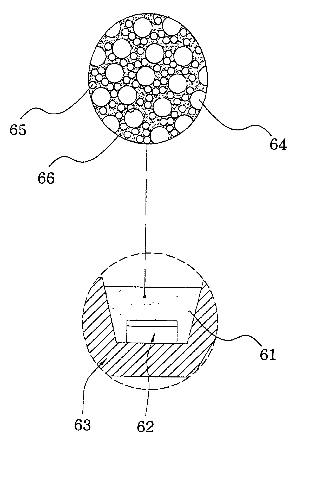
[0027] As in FIG. 6, the light-mixing layer 61 according to one embodiment of the present invention is placed on a chip cup 63, and it can mix with an epoxy and enclose a LED chip 62 (an example of a light source) for completely absorbing the light emitted from the LED chip 62. The light-mixing layer 61 is composed of light-scattering particles 64, phosphor particles 65 and diffuser particles 66. The light-scattering particles 64 could be made of quartz, glass or other polymeric transparent materials, the phosphor particles 65 could be made of YAG phosphor particles and the diffuser particles 66 could be made of BaTiO.sub.3, Ti.sub.2O.sub.3 and SiO.sub.x. After a baking or UV line illumination, the light-scattering particles 64, phosphor particles 65 and diffuser particles 66 will be arranged in a particle-interlaced order by the methods of inertial force, expressure, condensation, etc.

[0028] In FIG. 7, a portion of light emitted from the LED chip 62 changes its ongoing directions b...


PUM


Abstract

The present invention discloses a light-mixing layer and method. At the manufacturing stage, the present invention arranges the particles of the composition in the light-mixing layer in an particle-interlaced order, and makes the light-mixing layer excite another wavelength after absorbing the light emitted from a light source. These two kinds of lights are mixed in the light-mixing layer to obtain a complete light diffusion, light transformation and light mixture to generate a light source with a high uniformity, high brightness and stable color temperature.

Description

[0001] 1. Field of the Invention[0002] The present invention relates to a light-mixing device, particularly to a light-mixing layer and method.[0003] 2. Description of Related Art[0004] Recently, LED (Light-Emitting Diode) components have been popularly used in daily life. Due to the advantages of a small profile, low power consumption, low heat dissipation and long life, LED components have gradually replaced conventional lamps to act as a lighting device. Especially with successful development of a highlight LED and white light LED component, more and more large screen LED displays and indoor ruminants utilize LED components for luminescing, LED components will therefore become more widely used in the future.[0005] A known LED component disclosed in a U.S. Pat. No. 5,998,925 is entitled "LIGHT EMITTING DEVICE HAVING A NITRIDE COMPOUND SEMICONDUCTOR AND A PHOSPHOR CONTAINING A GARNET FLUORESCENT MATERIAL". The prior LED component includes an LED chip, a phosphor and epoxy, and it u...

Claims


Application Information

Patent Timeline
Patent Type & Authority Applications(United States)
IPC IPC(8): H01L33/50H01L33/56
CPCH01L33/501H01L33/56H01L2933/0091H01L2224/48091H01L2224/48247H01L2224/48257H01L2924/181
Inventor HO, WEN-CHIH
Owner HO WEN CHIH
Why Eureka
Try Eureka