
System and method for a high bandwidth servo system

a servo system and high bandwidth technology, applied in the direction of instruments, recording signal processing, disposition/mounting of heads, etc., can solve the problems of increasing data may be erroneously read, and existing formats become less practical, so as to reduce the overhead of servos

Inactive Publication Date: 2003-03-06
EMC CORP
View PDF16 Cites 58 Cited by
  • Summary
  • Abstract
  • Description
  • Claims
  • Application Information

AI Technical Summary

Benefits of technology

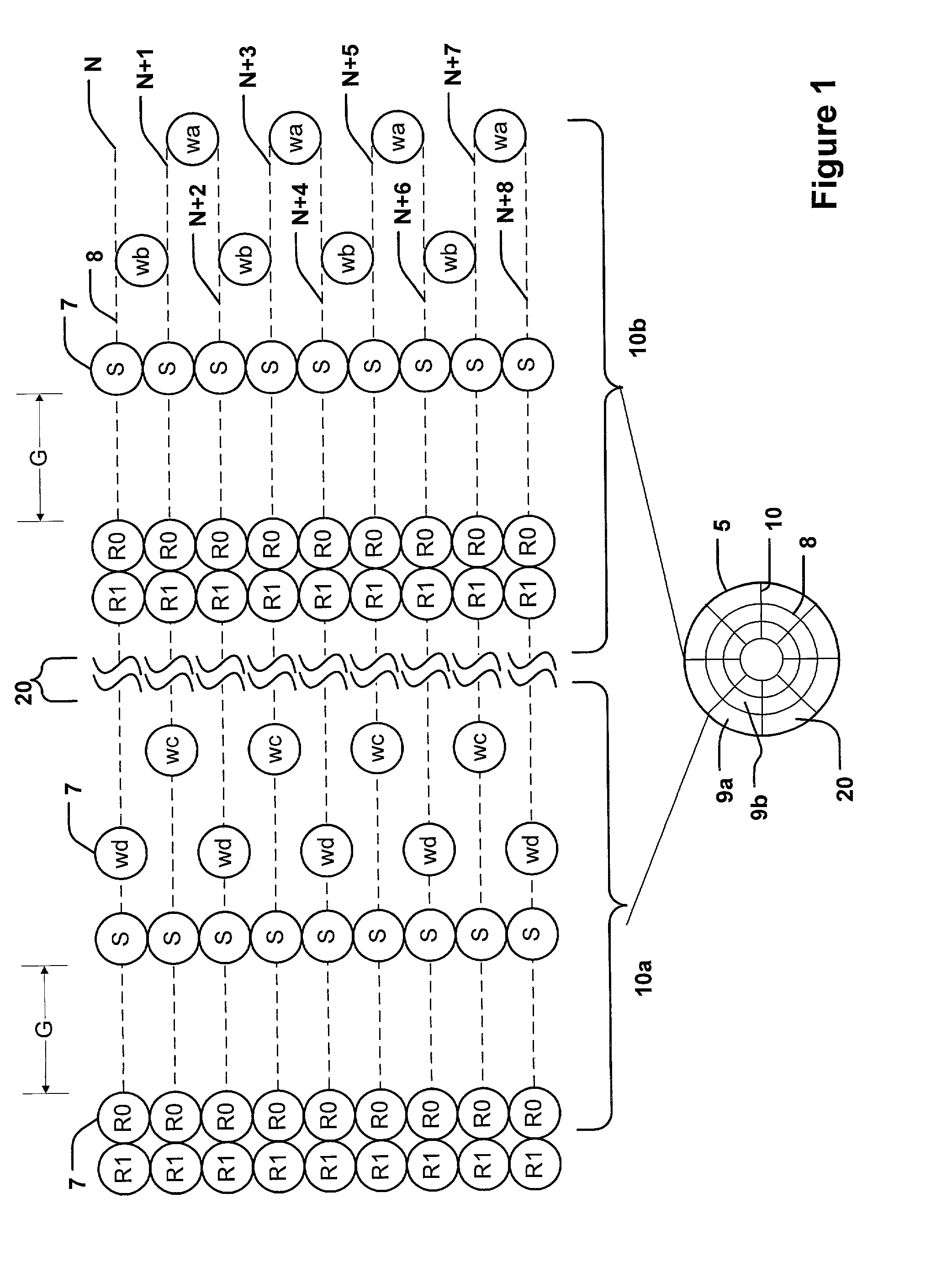
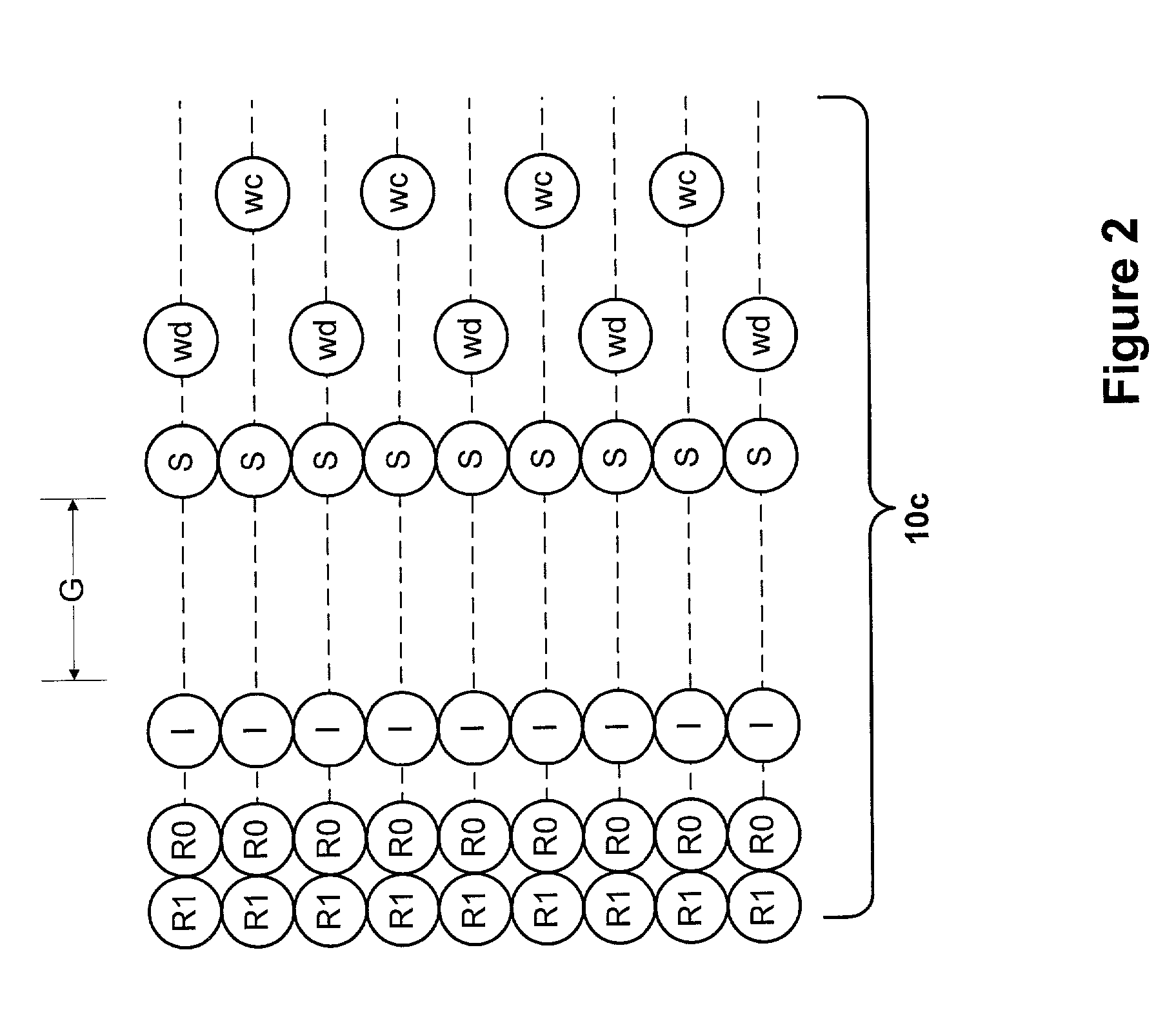
[0017] According to another aspect of the present invention, a storage medium includes a plurality of tracks. Each track includes a plurality of data sectors and a plurality of servo sectors. The servo sectors do not have identical lengths. A first set of servo sectors has a first length and a second set of servo sectors has a second length. The first length is different from the second length. In particular, each servo sector has a synchronization gap. The length of the synchronization gap of the first servo sectors is different from the length of the synchronization gap of the second servo sectors. In one embodiment, the length of the servo gap of the first servo sector is less than seven servo cycles and the length of the servo gap of the second servo sector is about one servo cycle. The long synchronization gap allows an unsynchronized reading device to recognize a servo sector and synchronize. The short synchronization allows a synchronized reading device to remain synchronized and decreases servo overhead.

Problems solved by technology

If the tracks are not precisely followed with appropriate position and clocking speed, data may be erroneously read.
Various information formats have been employed; however, as storage density increases, existing formats become less practical.
Applying the embedded servo technique that is typically used for magnetic storage medium to an optical storage medium (which typically has a higher storage density), provides several design challenges.
First, a straightforward application of known servo marks to an optical storage medium creates a large amount of servo overhead.
That is, the ratio of servo mark area to data mark area may become unacceptable, as described in more detail below.
This is an undesirable and sometimes unacceptable amount of servo overhead.
Further, in magnetic storage media today, a new data synchronization field occurs after every servo mark and increases servo mark overhead.
If more servo marks are added to increase the servo bandwidth the re-synchronization field overhead is even worse.
If the reading device becomes mis-aligned with the data track, then the reading device may begin to incorrectly read the data marks.
However, including both types of wobble marks in one servo sector increases the size of the servo sector.
This technique, while providing some benefit, may create an unacceptable amount of servo overhead in a high density storage medium.
This can reduce recovery time if the reading device loses track of its radial position.
However, this dedicated field increases the size of the servo sector and if applied to a high sample rate, high density storage device, may increase servo overhead to an unacceptable level.
It is desired to have the maximum amount of data on a storage medium; however, without enough servo sectors, the data sectors may not be read accurately.
However, if too few servo marks are used, a reading device may not be able to accurately read the data marks from the storage medium.
As can be seen, as the density of information stored on a storage medium becomes greater, the issue of servo mark overhead becomes critical.
Long servo marks may cause a reading device to become unsynchronized within a servo sector and if this occurs, the reading device requires a predefined data resynchronization pattern that increases the overhead of retrieving data.
Applying a conventional servo mark format to a high sample rate, high density storage medium may result in excessive servo mark overhead, thereby reducing the amount of storage available for data marks.
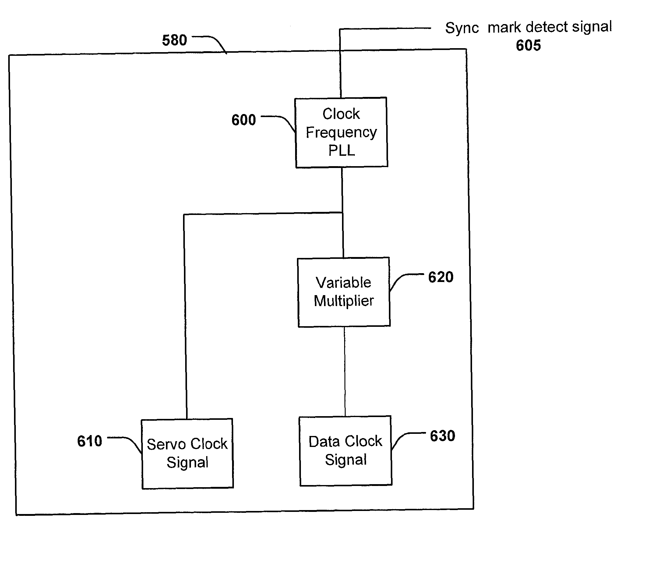
Therefore, multiplying the data clock by a constant does not provide a servo clock that functions for all zones.

Method used


Image

  • System and method for a high bandwidth servo system
  • System and method for a high bandwidth servo system
  • System and method for a high bandwidth servo system

Examples


Embodiment Construction

[0031] The present invention is directed to a servo sector format for a high bandwidth servo system and a system and method for using the servo sector format.

[0032] Certain terminology may be used in the following description for convenience only and is not considered to be limiting. For example, the words "left", "right", "top", and "bottom" designate directions in the drawings to which reference is made. Likewise, the words "inwardly" and "outwardly" are directions toward and away from, respectively, the geometric center of the referenced object. The terminology includes the words above specifically mentioned, derivatives thereof, and words of similar import.

[0033] FIG. 1 is an exploded view of servo marks of a storage medium, in accordance with one embodiment of the present invention. As shown in FIG. 1, storage medium 5 includes a plurality of substantially concentric tracks 8 located at circumferentially spaced intervals on storage medium 5. Each track 8 includes a plurality of...


PUM


Abstract

A storage medium is provided having a relatively large number of relatively small servo sectors. The storage medium includes a plurality of tracks. Each track includes a plurality of data sectors and a plurality of servo sectors. Each servo sector includes a plurality of servo marks and a synchronization gap. A plurality of first servo sectors includes a synchronization gap having a first length and a plurality of second servo sectors includes a synchronization gap having a second length. The first length is different from the second length, whereby, an unsynchronized reading device may recognize the longer synchronization gap and synchronize to the servo sector and a synchronized reading device may remain synchronized by recognizing the shorter synchronization gap.

Description

[0001] The present invention generally relates to the field of storage media, more particularly, the present invention relates to a servo sector format for a high bandwidth servo system and a system and method for using the servo sector format.[0002] A storage medium stores data for use by an electronic device having a reading device. Common examples of storage media include floppy disks, optical disks, hard disks, and the like. Common examples of a reading device are a floppy disk drive, a hard disk drive, and the like. A typical storage medium may be formatted to contain thousands of "tracks" of information, organized as concentric rings on the storage medium surface. These tracks must be precisely followed by the electronics of the reading device during reading and writing of data to / from the storage medium surface. If the tracks are not precisely followed with appropriate position and clocking speed, data may be erroneously read. Information is typically encoded on the storage m...

Claims


Application Information

Patent Timeline
IPC IPC(8): G11B7/007G11B7/09
CPCG11B7/00745G11B7/0938
Inventor SHELTON, BOYDMONROE, CHARLIE M.
Owner EMC CORP
Learn More