
Temperature control system for humidity sensor

a temperature control system and humidity sensor technology, applied in electrical control, exhaust treatment electric control, separation process, etc., can solve the problems of hydrocarbons which cannot be desorbed and permanently remain in the adsorbent, deterioration of the adsorbent, and small holes in the adsorben

Inactive Publication Date: 2003-03-06
HONDA MOTOR CO LTD
View PDF16 Cites 8 Cited by
  • Summary
  • Abstract
  • Description
  • Claims
  • Application Information

AI Technical Summary

Benefits of technology

[0013] According to this temperature control system for a humidity sensor, the heater control means causes the heater to operate when the temperature of the sensor element detected by the temperature-detecting means is higher than a first predetermined temperature, whereby the sensor element is heated. Thus, the heater is operated when the sensor element is in a high temperature condition, so that it is possible to efficiently burn and eliminate impurities attached to the sensor element. This makes it possible to properly restore detection accuracy of the humidity sensor.
[0029] According to this preferred embodiment, the determination of degradation of the adsorbent is carried out after the engine operating with supply of a mixture at or in the vicinity of the stoichiometric air-fuel ratio has stopped. When the air-fuel ratio of the mixture is at or in the vicinity of the stoichiometric air-fuel ratio, the amount of unburned components in exhaust gases is more steady or substantially fixed than when the air-fuel ratio of the mixture is on a richer or leaner side, and hence the determination of degradation of the adsorbent is accurate when it is carried out after the engine has stopped after operating with supply of a mixture at or in the vicinity of the stoichiometric air-fuel ratio. Moreover, when the air-fuel ratio of the mixture is at or in the vicinity of the stoichiometric air-fuel ratio, the amount of moisture in exhaust gases is relatively large with little variation, and hence the atmosphere in which the humidity sensor is operating after the engine operated in such a condition and then stopped is also relatively high in humidity with little variation, which is suitable for the determination of degradation of the adsorbent. Therefore, the degradation determination can be accurately carried out in this state.

Problems solved by technology

However, the amount of hydrocarbons which could not be desorbed and permanently remain in the adsorbent may progressively increase or the small holes of the adsorbent may be destroyed by a long-term use thereof.
This results in the degradation of the adsorbent to lower an adsorbing capacity of the adsorbent for adsorbing hydrocarbons.
In this case, the humidity of the exhaust gases cannot be detected properly, and the degree of degradation of the adsorbent cannot be detected properly, either.
Even if such impurities have been attached, so long as it is not presumed that condensation has been formed, the above temperature control is not carried out, resulting in the degraded detection accuracy of the humidity sensor.
Further, since the heater is simply operated for the predetermined time period, there is a fear that the impurities cannot be sufficiently eliminated, e.g. depending on a temperature condition of the exhaust system.
Moreover, since the sensor element is suddenly heated by the heater from a state having condensation formed thereon, the temperature of the sensor element sharply rises from a low temperature, which can cause cracking of the sensor element.

Method used


Image

  • Temperature control system for humidity sensor
  • Temperature control system for humidity sensor
  • Temperature control system for humidity sensor

Examples


Embodiment Construction

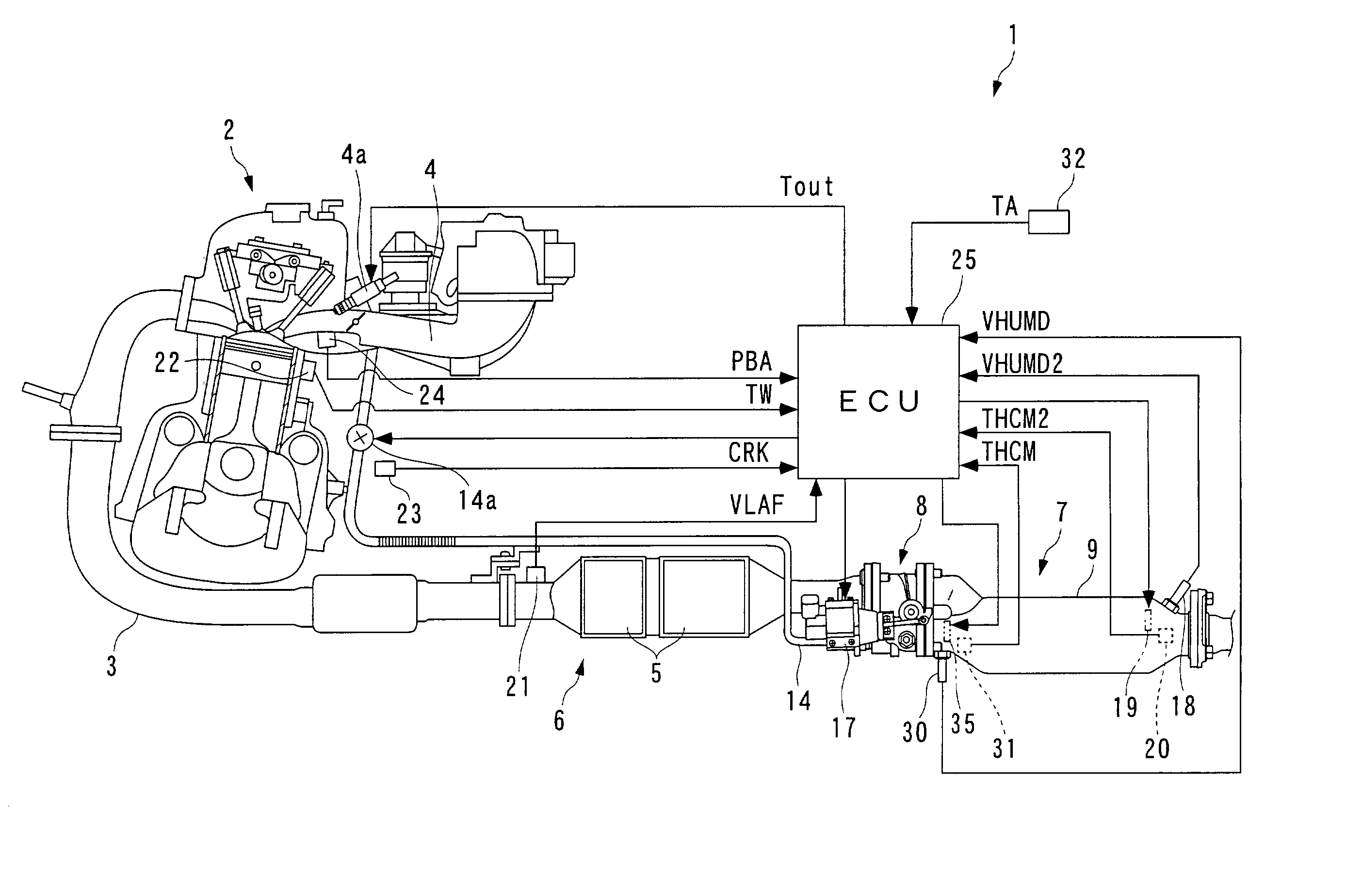
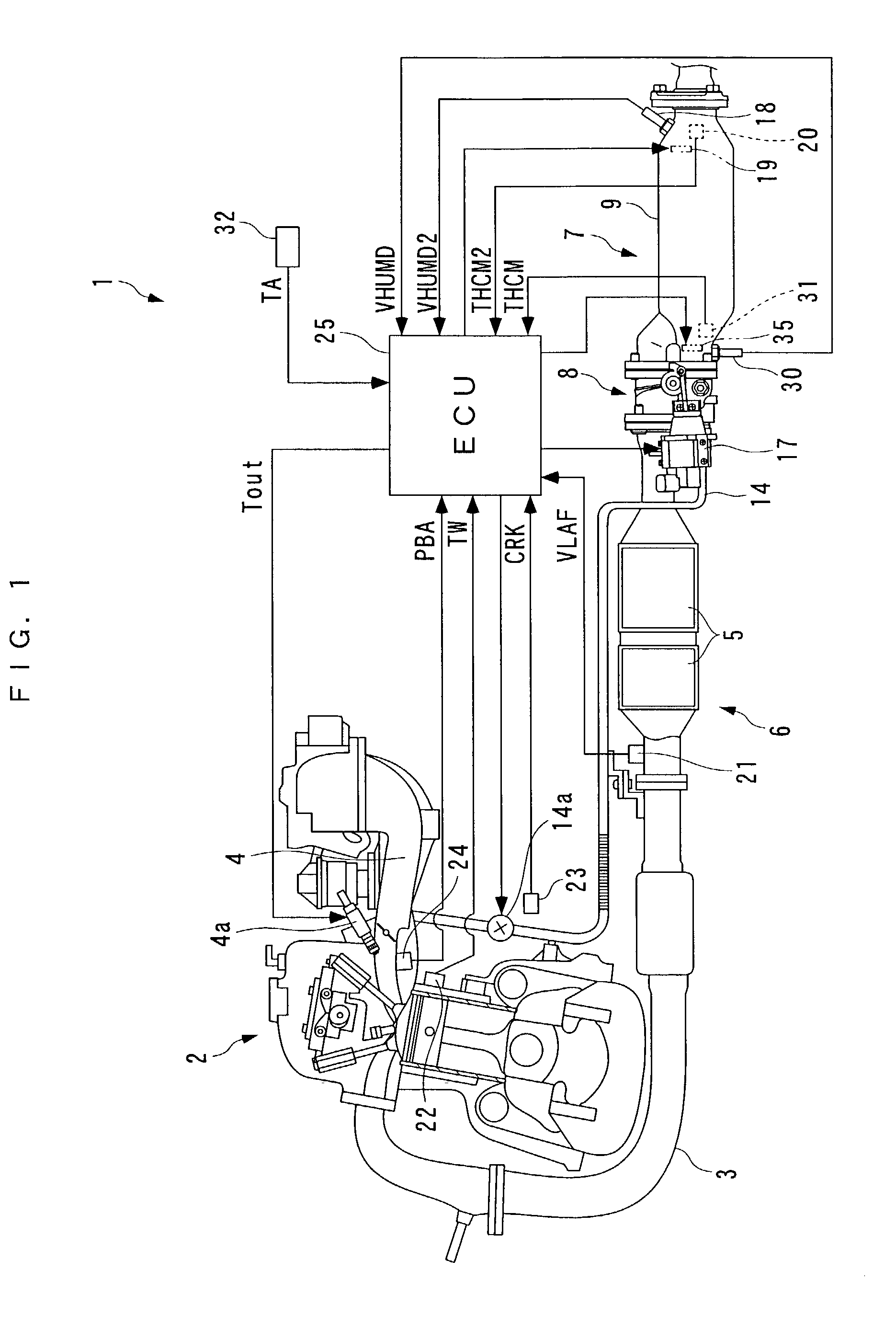
[0038] The invention will now be described in detail with reference to the drawings showing a preferred embodiment thereof. Referring first to FIG. 1, there is schematically shown the arrangement of an internal combustion engine 2 (hereinafter simply referred to as "the engine 2") to which is applied a temperature control system 1 for a humidity sensor (hereinafter simply referred to as "the control system 1"), according to the embodiment of the present invention. This engine 2 is e.g. a four-cylinder four-cycle engine installed on a vehicle, not shown, which has an idle stop feature. Further, the engine 2 includes an intake pipe 4 having injectors 4a provided for respective cylinders, and the fuel injection time period Tout of each injector 4a is controlled by an ECU 25, referred to hereinafter.

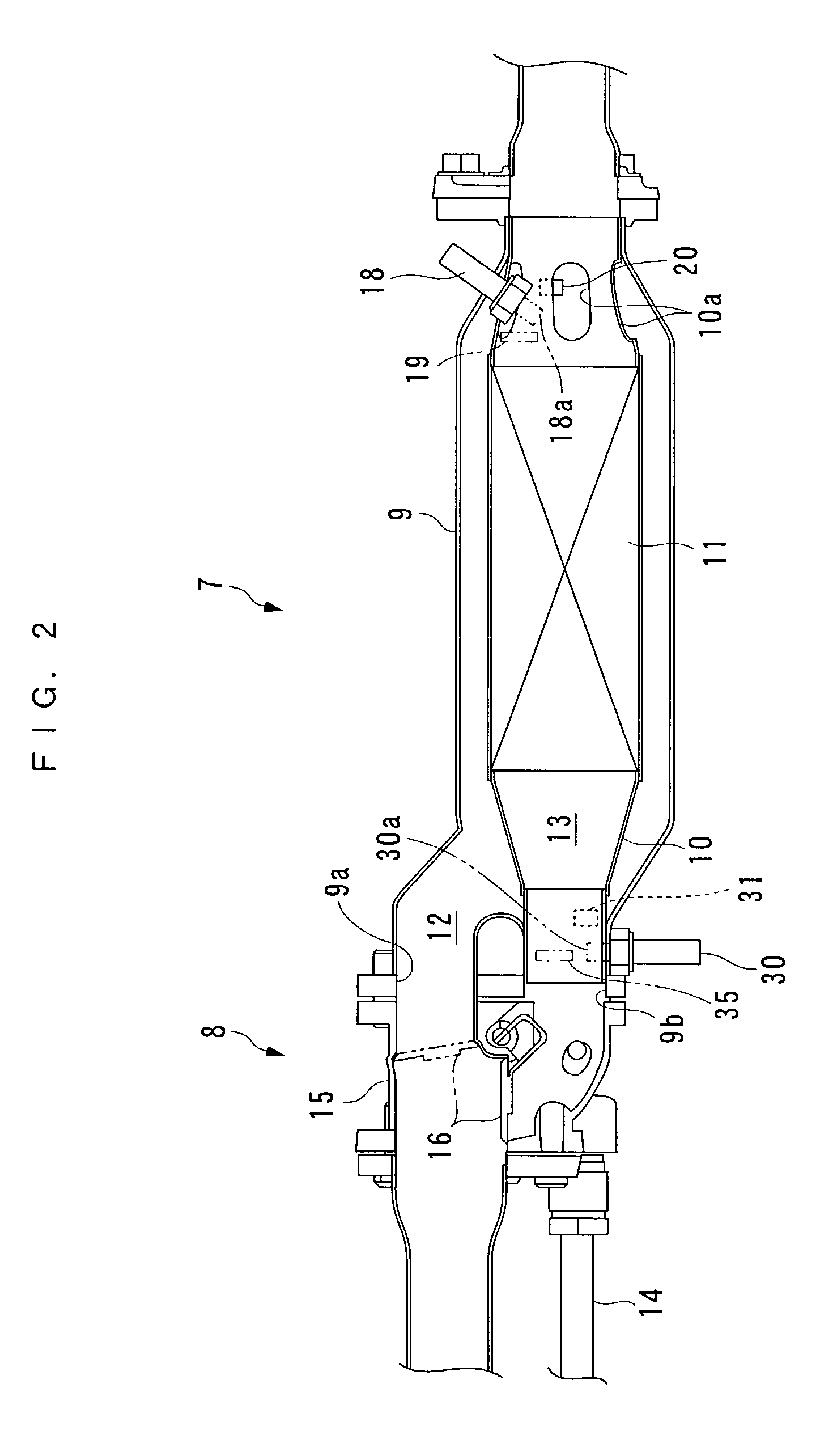
[0039] In an intermediate portion of an exhaust pipe 3 of the engine 2, a catalytic device 6 having a three-way catalyst 5, and a hydrocarbon adsorber 7 for adsorbing hydrocarbons are arrang...


PUM


Abstract

There is provided a temperature control system for a humidity sensor, which is capable of eliminating impurities attached to a sensor element of the sensor efficiently and sufficiently while preventing the sensor element from being cracked due to heat generated by a heater in a state of condensation formed thereon, and suppressing attachment of impurities to the sensor element, thereby making it possible to preserve an excellent detection accuracy of the humidity sensor. The temperature control system controls the temperature of the sensor element of the humidity sensor arranged in an exhaust pipe for detecting humidity within the exhaust pipe. A heater heats the sensor element. The temperature of the sensor element is detected. When the detected temperature of the sensor element is higher than a predetermined temperature, said heater is operated

Description

[0001] 1. Field of the Invention[0002] This invention relates to a temperature control system for controlling the temperature of a sensor element of a humidity sensor that is arranged in an exhaust pipe of an internal combustion engine for detecting humidity within the exhaust pipe.[0003] 2. Description of the Prior Art[0004] There has been proposed an internal combustion engine having an adsorbent arranged in an exhaust system thereof, for adsorbing hydrocarbons in exhaust gases. The adsorbent carries zeolite on its surface. When exhaust gases are passing through the adsorbent, the hydrocarbons contained therein enter small holes of the zeolite, thereby being adsorbed by the adsorbent. The adsorbent of this kind desorbs i.e. releases hydrocarbons once adsorbed thereby when it is heated by exhaust gases to a temperature equal to or higher than a predetermined temperature (e.g. 100 to 250.degree. C.). The desorbed hydrocarbons are recirculated to the engine e.g. via an EGR pipe. The ...

Claims


Application Information

Patent Timeline
IPC IPC(8): G01N27/12B01D53/72F01N3/00F01N3/08F01N3/18F01N3/20F01N3/24F01N11/00F01N13/08F02D41/04F02D41/14F02D41/22F02D45/00
CPCF01N3/0814F01N3/0835F01N3/0878F01N3/2053F01N11/00F01N2550/03F01N2560/028F01N2900/0422F02D41/1444F02D41/1456F02D41/1494F02D41/222F02D2200/0418G01N27/121Y02T10/40Y02T10/47
Inventor YAMAZAKI, HIDEHARUSATO, TADASHIHAGA, TAKASHIMIYAHARA, YASUYUKIUENO, MASAKIMACHIDA, KEI
Owner HONDA MOTOR CO LTD
Learn More