Refrigerant cycle system including two evaporators

a technology of refrigerant cycle and evaporator, which is applied in space heating and ventilation control systems, lighting and heating apparatus, heating types, etc., can solve the problems of reducing the durability of the compressor, affecting the efficiency of the compressor, and the amount of lubricating oil returned to the compressor may become insufficien

Inactive Publication Date: 2003-03-20
DENSO CORP
View PDF0 Cites 40 Cited by
  • Summary
  • Abstract
  • Description
  • Claims
  • Application Information

AI Technical Summary

Problems solved by technology

Therefore, a lubricating oil is stored in the low-pressure side refrigerant pipe at an outlet of the rear evaporator, and an amount of the lubricating oil returned to the compressor becomes short, thereby generating lubrication failure in the compressor, and reducing durability of the compressor.
However, in this refrigerant cycle system, there is not described regarding a control for preventing the oil return shortage when the compressor is operated with a small capacity.
Accordingly, in this refrigerant cycle system, when the refrigerant amount discharged from the compressor is made small, the amount of the lubricating oil returned to the compressor may become insufficient.
Further, in the refrigerant cycle system, when an electric compressor is used as the compressor and the discharge capacity of the compressor is controlled by controlling a rotation speed of its motor, the amount of the oil returned to the compressor becomes short when the rotation speed of the motor is decreased for reducing the flow amount of refrigerant in the refrigerant cycle system.

Method used


Image

  • Refrigerant cycle system including two evaporators
  • Refrigerant cycle system including two evaporators
  • Refrigerant cycle system including two evaporators

Examples


first embodiment

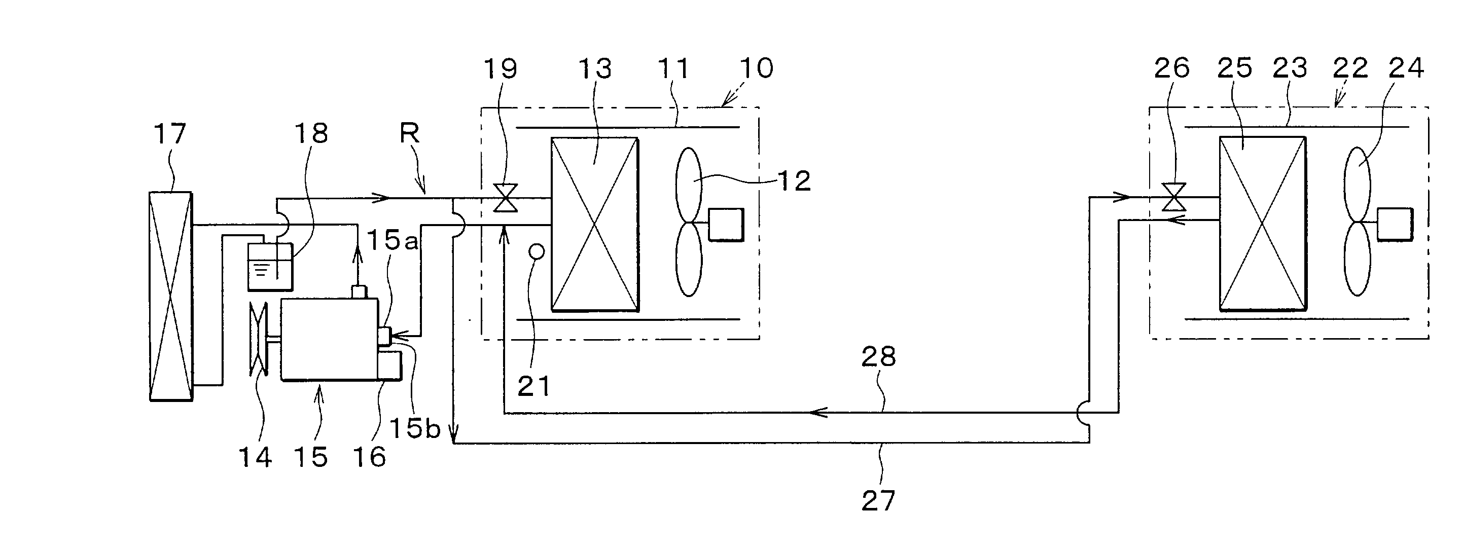
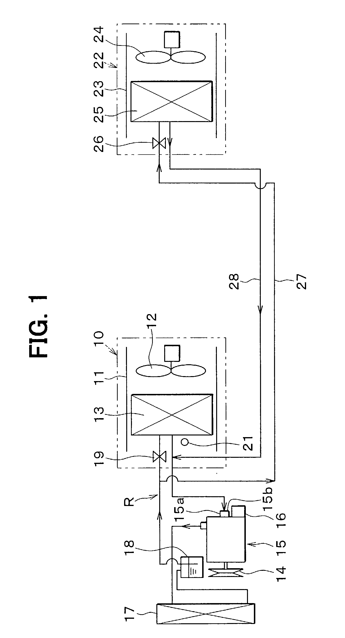
[0027] In the first embodiment, a refrigerant cycle system R shown in FIG. 1 is typically used for a vehicle air conditioner. In the refrigerant cycle system, a front air-conditioning unit 10 shown in FIG. 1 is disposed inside a dashboard (not shown) at the most front side in the passenger compartment. The front air-conditioning unit 10 is for performing air-conditioning operation for a space at a front seat side in a passenger compartment of the vehicle. The front air-conditioning unit includes a case 11 defining an air passage through which air is blown toward the front seat side in the passenger compartment. A front blower 12 is disposed in the case 11 at an upstream air side. The front blower 12 blows inside air or / or outside air selectively introduced from an inside-outside air switching box (not shown). At a downstream air side of the front blower 12, a front evaporator (first evaporator) 13 of the refrigerant cycle system R is disposed as a cooling heat exchanger for cooling ...

second embodiment

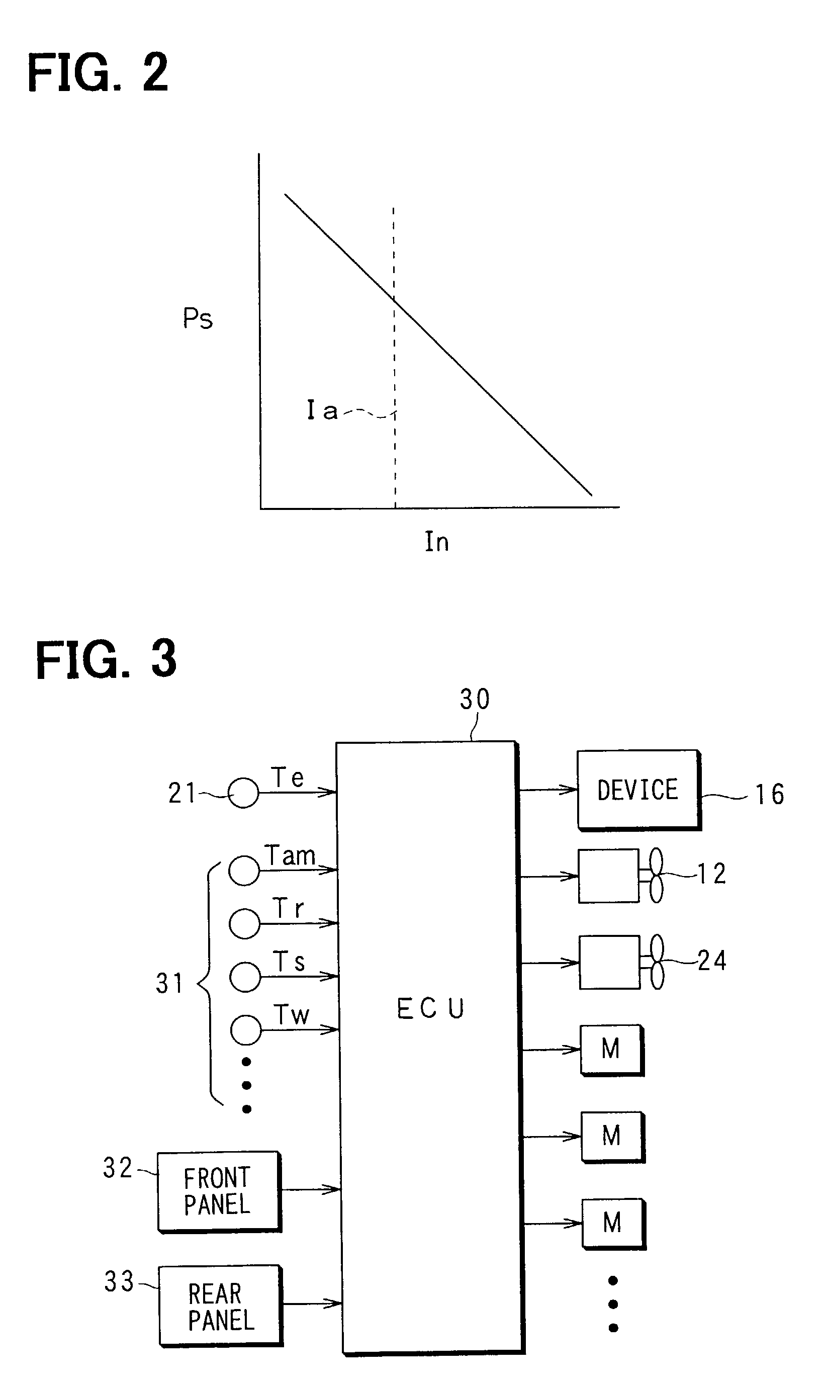
[0055] In the variable displacement compressor 15 according to the above-described first embodiment, target value of the suction pressure Ps is set based on the control current In of the variable displacement device 16 as shown in FIG. 2, and the discharge capacity is changed so that the suction pressure Ps (low-pressure side refrigerant pressure) of the compressor 15 can be maintained at the target value. However, in the second embodiment, a target discharge amount Gro of refrigerant discharged from the compressor 15 is set based on the control current In of the variable displacement device 16 as shown in FIG. 10, and the discharge capacity of the compressor 15 is changed (adjusted) so that the discharge amount of the compressor 15 can be maintained at the target discharge amount Gro. Specifically, in the second embodiment, a throttle portion is provided at the discharge side of the variable displacement compressor 15. Here, a pressure difference generated between front and rear si...

third embodiment

[0058] In the variable displacement compressor 15 according to the above-described first and second embodiments, the discharge capacity of the compressor 15 is changed, so that the flow amount of refrigerant discharged from the compressor 15 is changed. In the third embodiment, an electric compressor 15 shown in FIG. 11 is used. In the electric compressor 15, a motor 15d and a compression mechanism portion 15e driven by the motor 15d are integrated to each other. Specifically, the motor 15d is a three-phase alternating-current (AC) motor, and the compression mechanism portion 15e is a scroll compression mechanism. A frequency of a three-phase AC power source provided in the motor 15d is controlled by an inverter 15f, so that the rotational speed of the motor 15d is controlled. The flow amount of refrigerant discharged from the compressor 15 can be changed in accordance with the rotational speed of the motor 15d. The inverter 15f is controlled by the output signals from the ECU 30.

[0...


PUM


Abstract

A refrigerant cycle system includes a variable displacement compressor, and first and second evaporators disposed in parallel. In the refrigerant cycle system, it is determined whether a refrigerant flow amount from the compressor is in a low flow amount area when first and second blowers for blowing air to the first and second evaporators are operated at the same time. When it is determined that a predetermined time passes after the refrigerant flow amount is determined to be in the low flow amount area, the operation of the compressor is forcibly switched between a large discharge capacity and a small discharge capacity. Accordingly, it can prevent oil returning to the compressor from being short due to the operation of the compressor in the low flow amount area.

Description

[0001] This application is related to and claims priority from Japanese Patent Applications No. 2001-287312 filed on Sep. 20, 2001 and No. 2002-180153 filed on Jun. 20, 2002, the contents of which are hereby incorporated by reference.[0002] 1. Field of the Invention[0003] The present invention relates to a refrigerant cycle system including first and second evaporators disposed in parallel. The refrigerant cycle system is suitably used for a vehicle air conditioner including a front air-conditioning unit for performing air-conditioning operation for a front seat area in a passenger compartment, and a rear air-conditioning unit for performing air-conditioning operation for a rear seat area in the passenger compartment.[0004] 2. Description of Related Art[0005] Recently, the market request for a minivan has been increased. In the minivan, since the capacity of a passenger compartment is large, a vehicle air conditioner is required to have a large air-conditioning capacity. Therefore, ...

Claims


Application Information

Patent Timeline
Patent Type & Authority Applications(United States)
IPC IPC(8): B60H1/32F24F11/02F25B1/00F25B5/02F25B49/02
CPCB60H1/3205B60H1/3214B60H1/323B60H2001/3261B60H2001/3272B60H2001/3275F25B5/02F25B49/022F25B2500/16F25B2600/021
Inventor OHYA, SHIGEKI
Owner DENSO CORP
Why Eureka
Try Eureka