
Method of installing a tubular element

a tubular element and installation method technology, applied in the direction of cables, cable installation in underground tubes, instruments, etc., can solve the problems of retaining solid residues along the duct, interfering with subsequent cleaning operations, and long operation, and achieve the effect of low cos

Inactive Publication Date: 2003-03-20
ALCATEL LUCENT SAS
View PDF10 Cites 2 Cited by
  • Summary
  • Abstract
  • Description
  • Claims
  • Application Information

AI Technical Summary

Benefits of technology

[0006] An object of the present invention is to eliminate the drawbacks of the prior art, and to this end it provides a method of installing a tubular element in an existing cavity, which method is quick and of low cost, while nevertheless ensuring fixing that is longer-lasting.
[0011] In the method of the present invention, both the tubular element and its fixing means are inserted simultaneously into the cavity. The advantage of this method is that it avoids the need to put the fixing means for the tubular element previously into place on the inside wall of the cavity. In addition, the method is less expensive than a method that requires the entire cavity to be lined.
[0012] The unit formed by the tubular element associated with its fixing means is inserted in the cavity. The unit is preferably placed on the bottom of the cavity. In this way, there is no need to use means for holding the unit in a selected position until fixing has been ensured between the tubular element and the inside wall. This makes the method faster and easier to perform. The tubular element may be made of a plastics material, such as polyethylene, or out of a metal such as steel, which presents the advantage of withstanding rodents. When hollow, the tubular element can be filled with a liquid during the activation treatment in order to counteract the buoyancy thrust from the fixing compound while it is in the liquid state. When the tubular element is to be embedded completely in the fixing compound, it is preferable to use a corrugated metal tubular element which presents a saving in weight. Otherwise, the tubular element may be covered in metal in part only so as to be capable of withstanding rodents.
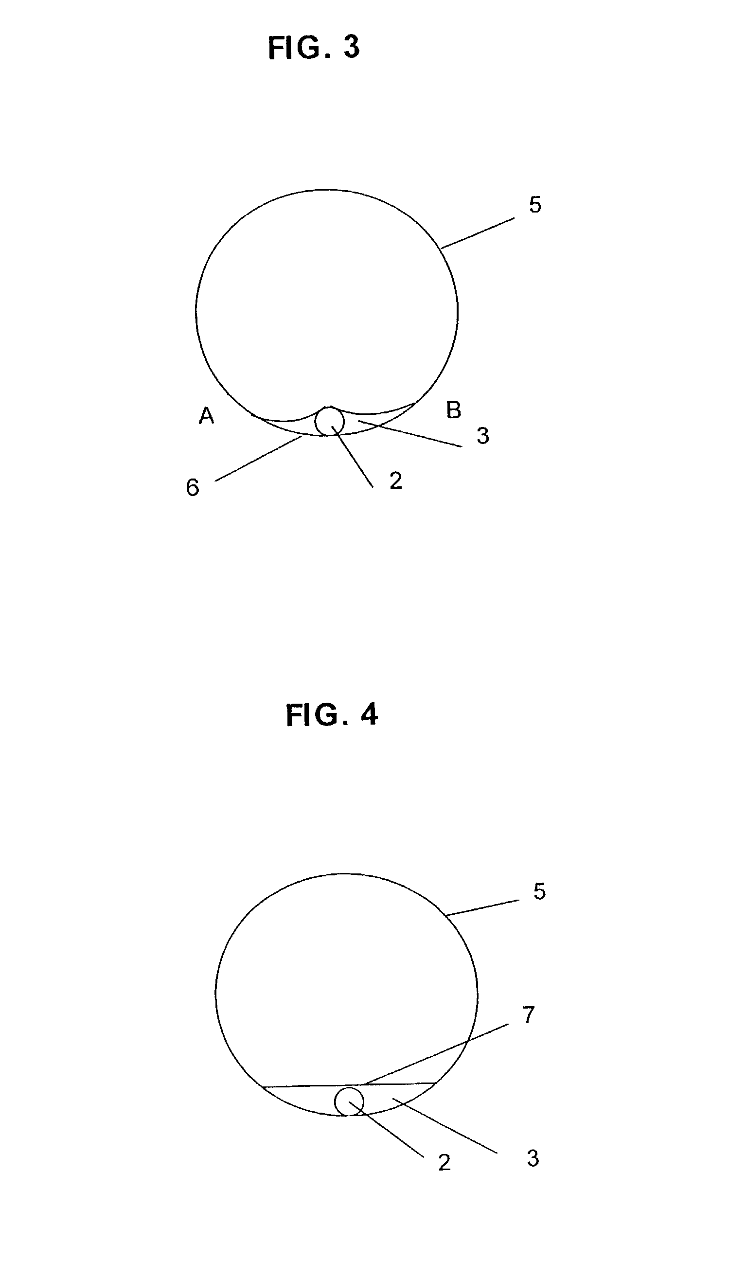
[0018] In a particular implementation of the invention, said activation treatment causes said fixing compound to change from the solid state to the liquid state, and preferably into a viscous liquid state. The fixing compound is then in the form of a liquid of consistency presenting thickness that depends on the operating conditions that have been selected as a function of the intended result. Under such circumstances, the compound covers that portion of the inside wall that is placed beneath the tubular element, and also both sides of the tubular element, which is thus fixed in reliable and long-lasting manner.
[0019] If the quantity of fixing compound and the operating conditions make this possible, the compound may fill the bottom of the cavity, possibly even covering the tubular element completely. Any irregularities in the wall at the bottom of the cavity are thus hidden, and the bottom of the cavity then presents a surface that is horizontal, plane, and relatively smooth.
[0021] The method of the invention presents numerous advantages. It is simple to implement and it is quicker than known methods. In particular it avoids the need for fixing means to be installed beforehand since the fixing means are inserted simultaneously with the tubular element. Roughnesses are reduced, thereby serving both to make the cavity easier to clean and also avoiding interfering with flow within the cavity, in particular the flow of sewage or of rain water. The method can be used in any type of cavity regardless of its shape, even if the wall presents projections. Indeed, the method presents the advantage of hiding defects in the portion of the cavity wall on which the tubular element is fixed. Finally, when the tubular element is placed on the bottom of the cavity, then aging does not give rise to the unwanted consequences of the prior art method that relies on a lining that also covers the ceiling of the cavity.

Problems solved by technology

One problem lies in ensuring that such means are fixed strongly and durably to the wall of the cavity even though it can be made out of a variety of different materials.
A drawback of that type of method is the requirement for the fixing means to be put into place in advance, which constitutes an operation that is lengthy and sometimes difficult.
Such projections run the risk of retaining solid residues moving along the duct, and of interfering with subsequent cleaning operations.
Nevertheless, putting such a lining into place is lengthy and expensive since the entire surface of the cavity is covered in the adhesive material.
Furthermore, the adhesion of said lining on the wall deteriorates over time.
As a result the cable is no longer held properly, and portions of the lining can become detached, in particular they can become detached from the top portion of the cavity under the effect of gravity, thereby causing the cavity to be obstructed, at least in part.
That method is particularly expensive, firstly because the entire surface of the cavity is covered in the lining material, and secondly because of the large amount of external infrastructure that is required in order to spray the resin.
That method presents the drawback of not being applicable to a tubular element.
The quality with which the article is fixed to the wall by that method is not satisfactory since adhesion of the article on the wall involves only a relatively small portion of the periphery of the article, corresponding to the area of the hollow.
In addition, adhesion will inevitably deteriorate over time and the article will end up becoming detached from the wall.

Method used


Image

  • Method of installing a tubular element
  • Method of installing a tubular element
  • Method of installing a tubular element

Examples


Embodiment Construction

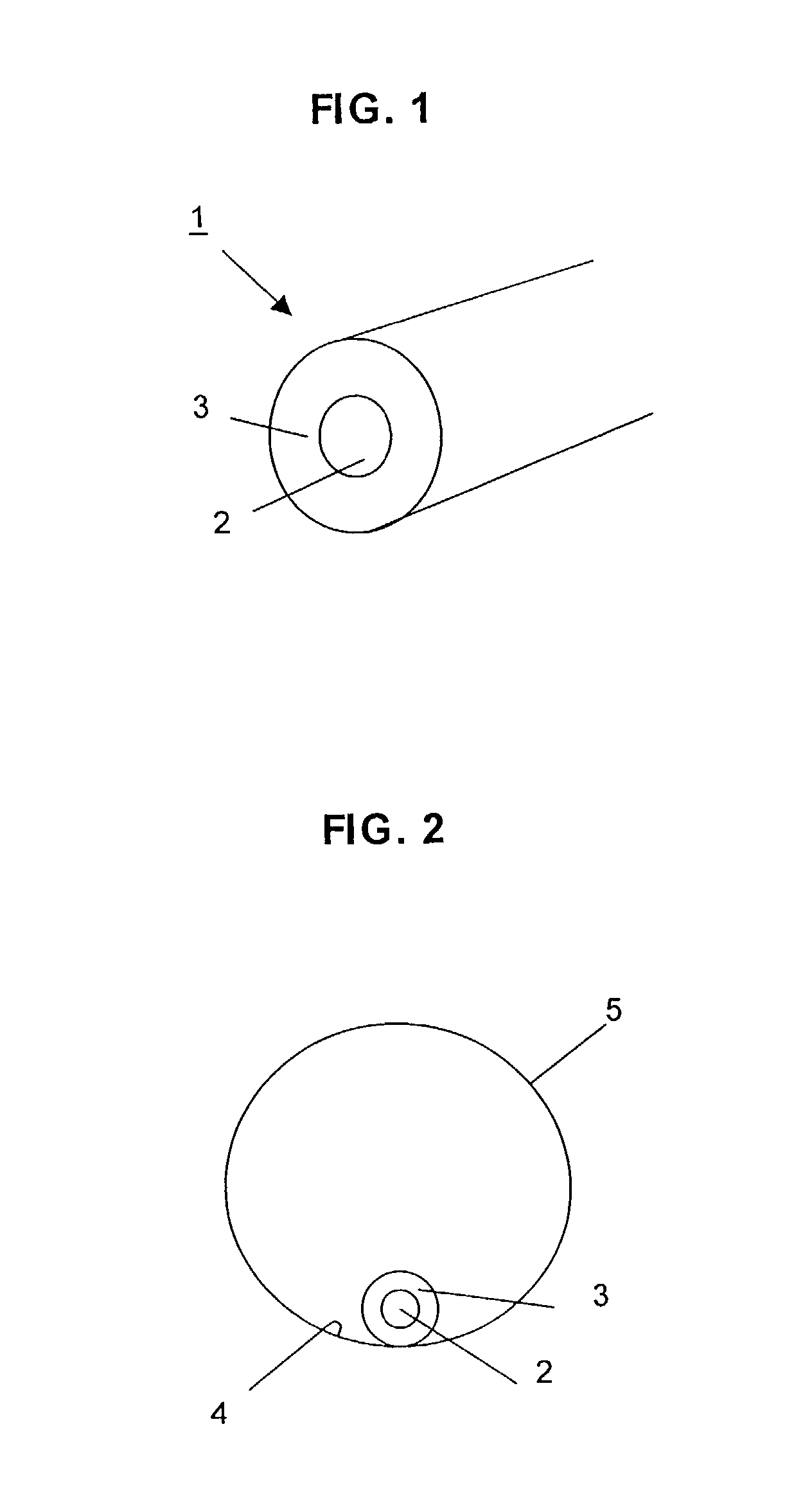
[0031] The unit 1 comprises a tubular element 2 coated in a thick layer of a fixing compound 3, as shown in FIG. 1. By way of example, the tubular element 2 is a hollow tube having a diameter of less than 10 mm, for receiving one or more cables, in particular optical fiber cables as used in telecommunications. Once the tube has been installed, cables placed within the tube can be changed or other cables can be added thereto without any need to repeat the operations involved in installing the tube. By way of example, the fixing compound 3 may be a hot-melt glue which is solid at operating temperatures.

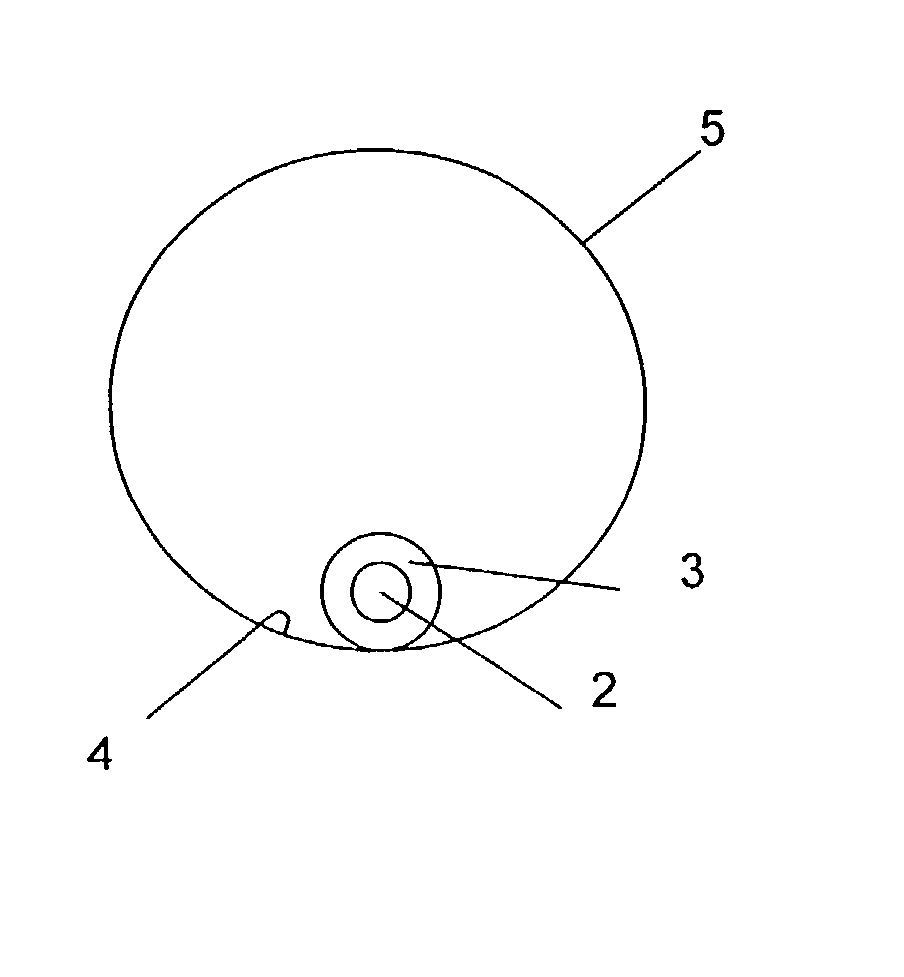
[0032] The unit 1 is inserted into the cavity in such a manner as to rest on the bottom 4 of the cavity whose own diameter is about 100 mm, as shown in FIG. 2. As a general rule, installing the unit 1 in the cavity 5 involves at least two stages. A first stage comprises exploring and cleaning the walls of the cavity, while a subsequent stage involves the unit 1 being installed in the ca...


PUM

PropertyMeasurementUnit
Temperatureaaaaaaaaaa
Lengthaaaaaaaaaa
Adhesivityaaaaaaaaaa

Abstract

The present invention provides a method of installing a tubular element in a cavity. The method comprises the following steps: preparing a unit comprising said tubular element and a layer of a fixing compound which covers the entire outer periphery of said tubular element, at least over a fraction of its length; positioning said unit along the inside wall of said cavity; and applying activation treatment to said compound in such a manner as to fix said tubular element to said inside wall. The unit is preferably placed on the bottom of the cavity.

Description

[0001] The present invention relates to a method of installing a tubular element in an existing cavity. The tubular element may be a cable or a pipe, and in particular it may be a hollow tube for receiving one or more cables. The cavity can be constituted in particular by a tubular cavity, for example a network of piping for collecting sewage or rain water. The invention relates more particularly to the operations that take place within non-pressurized underground tubular cavities of small diameter, in particular having a diameter of less than 200 millimeters (mm), such as a sewerage network or a drain pipe from a building, and in which direct visual and physical access is not possible.[0002] In the ordinary way, the tubular element is fixed to the inside wall of an inaccessible cavity by fixing means that are spaced apart regularly. The fixing means are fixed in advance on the inside wall of the cavity, usually along the top thereof, by means of a remotely guided device. One proble...

Claims


Application Information

Patent Timeline
IPC IPC(8): G02B6/50G02B6/46H02G1/06H02G1/08H02G3/04H02G3/30H02G9/06
CPCG02B6/508H02G1/08H02G9/06
Inventor HERRMANN, PETER FRIEDRICHMISTRY, KEKUWURIER, BERNARDGAUTHIER, PHILIPPER
Owner ALCATEL LUCENT SAS
Learn More