Downhole membrane separation system with sweep gas

a technology of membrane separation and sweep gas, which is applied in the direction of water cleaning, separation process, borehole/well accessories, etc., can solve the problems of inefficient filter arrangement of u.s. pat. no. 6,015,011 for separating hydrocarbons from contaminants, and high cost of above ground separation

Inactive Publication Date: 2003-03-20
CHEVROU USA INC
View PDF0 Cites 40 Cited by
  • Summary
  • Abstract
  • Description
  • Claims
  • Application Information

AI Technical Summary

Problems solved by technology

This above ground separation is costly.
Disposal of the removed contaminants may also present environmental problems.
However, the filter arrangement of U.S. Pat. No. 6,015,011 is inefficient in separating hydrocarbons from contaminants because of the arrangement of the membrane.
In this separator, a build up of the contaminants which have passed through the membrane will decrease the partial pressure driving force and decrease the efficiency of the separator.
However, the product that permeates the membrane is then either lost or must be recovered in another manner.
This two stage approach has the drawback that interstage compression of the gas stream is required.
Gas compressors are expensive in both capital and operating expense and require significant maintenance.
Furthermore, gas compression cannot be conveniently accomplished downhole.
Higher pressure ratios may require higher energy consumption to compress the feed, to recompress the permeate, or to generate a vacuum on the permeate side.
Pressure ratio is also limited by the operational strength of the membrane materials.
However, these methods are not feasible for downhole applications where pressure boosts or interstage compression are difficult.

Method used


Image

  • Downhole membrane separation system with sweep gas
  • Downhole membrane separation system with sweep gas
  • Downhole membrane separation system with sweep gas

Examples


example 2

Improvement of Separation with Sweep Gas

[0037] According to one example, a feed gas of 90% methane and 10% CO.sub.2 is fed to a CO.sub.2 selective membrane at a pressure of 1,000 psia and a flow rate of 1,000 scfm, with the raffinate pressure being held at 500 psia. We assume that the membrane is perfectly selective and permeates only CO.sub.2 and no methane. A countercurrent sweep of an inert gas, such as nitrogen at 500 psia and a flow rate of 400 scfm is introduced. CO.sub.2 can now be removed from the product gas down to a level of 2% CO.sub.2 content. This limit is a result of the overall mass balance and a limit on the driving force at the feed end of the membrane.

[0038] Clearly, the product purity has improved from 5% CO.sub.2 without the sweep gas to 2% CO.sub.2 with the use of the sweep gas.

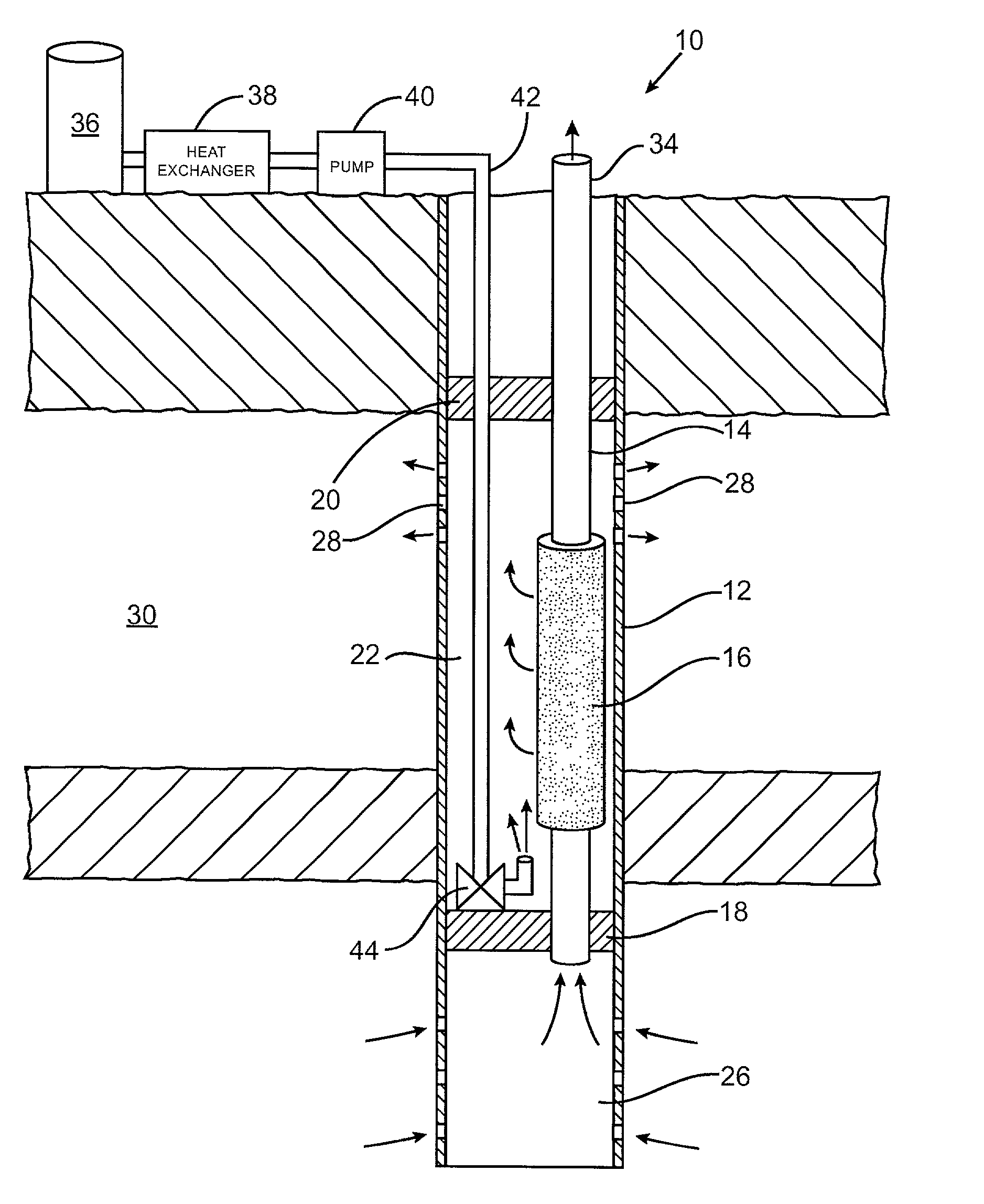
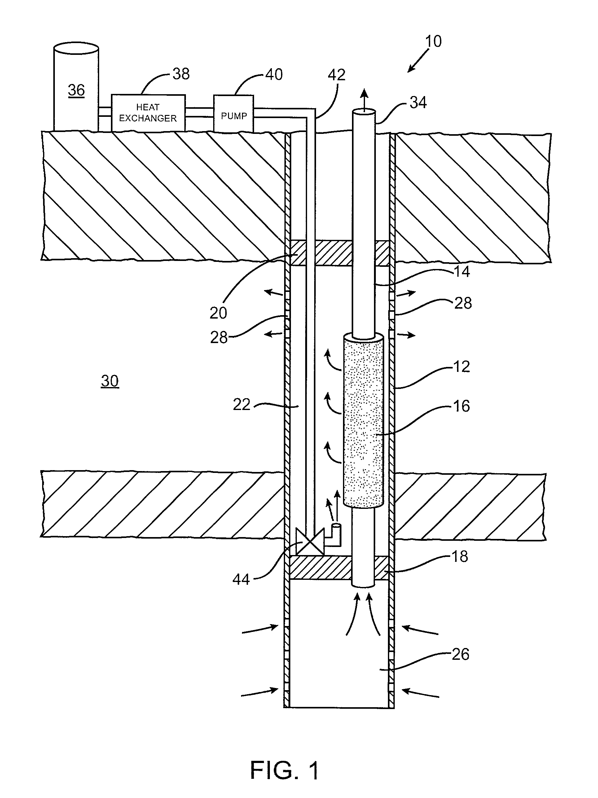
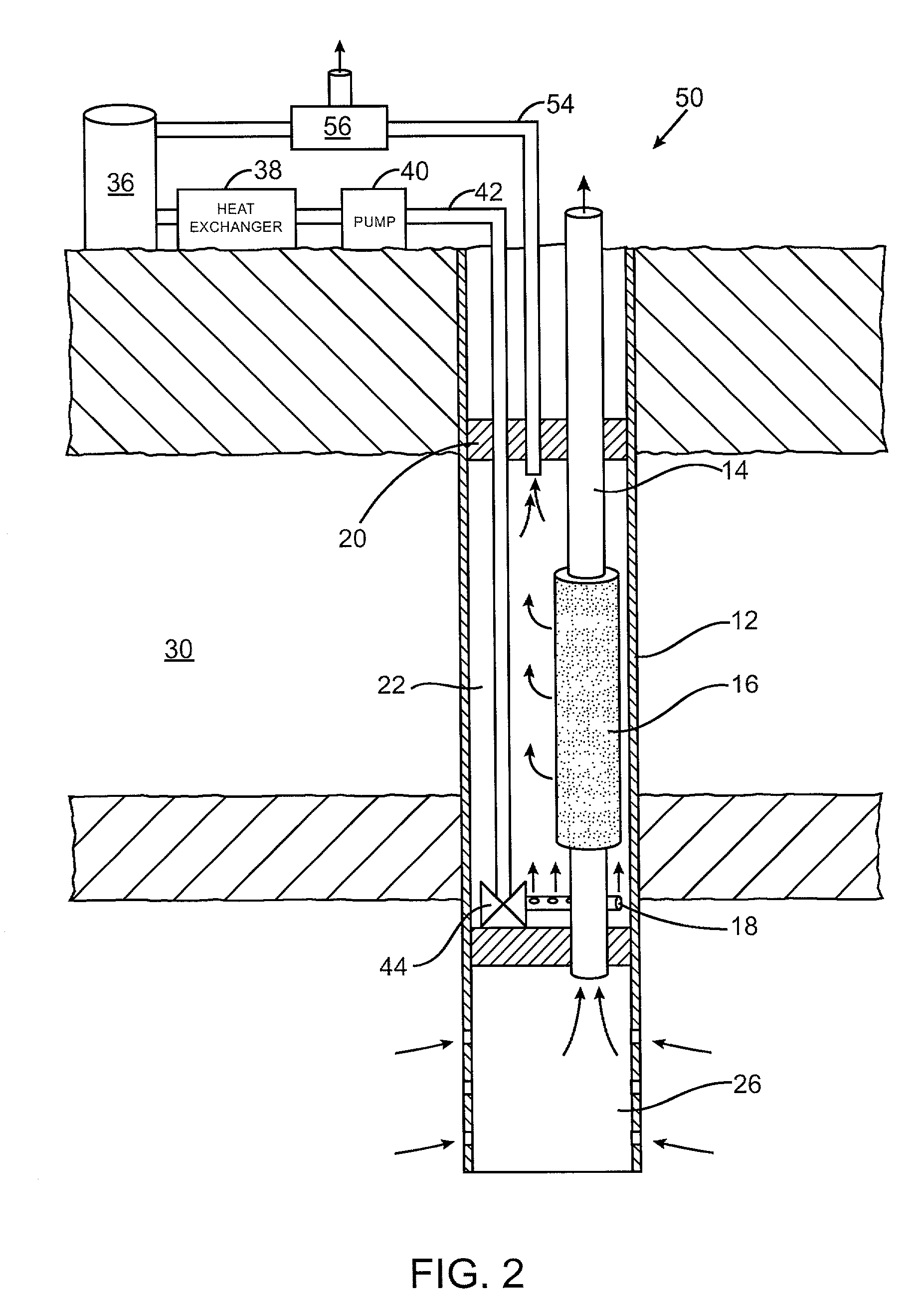
[0039] FIGS. 1-4 each illustrate a single tubular membrane 16 for purposes of illustration. However, the membrane separation systems 10, 50, 70, and 90 may include multiple membranes arr...


PUM

PropertyMeasurementUnit
partial pressureaaaaaaaaaa
temperatureaaaaaaaaaa

Abstract

One configuration of a separation system for separating hydrocarbons from contaminants downhole includes a tubular membrane having a fluid inlet end and a fluid outlet end. Between the fluid inlet end and the fluid outlet end of the membrane tube the membrane material selectively permeates contaminants, such as carbon dioxide, through the membrane while preventing the hydrocarbon from passing through the membrane achieving the downhole separation. A driving force of the membrane is increased by passing a sweep gas past the output side of the membrane during membrane separation to remove or dilute the contaminant at the output side of the membrane. The sweep gas improves the driving force of the membrane by increasing a partial pressure difference across the membrane.

Description

[0001] The invention relates to recovery of hydrocarbons from a wellbore, and more particularly, the invention relates to technology for separation of contaminants from hydrocarbons in a wellbore with a membrane separation system using a sweep gas to enhance separation.BACKGROUND OF THE INVENTION AND BRIEF DESCRIPTION OF THE RELATED ART[0002] Hydrocarbon gases and liquids are recovered from underground wellbores by drilling a wellbore into a hydrocarbon gas or liquid formation and withdrawing the materials under reservoir pressure or by artificial lifting. The fluids withdrawn from the reservoir consist of a combination of hydrocarbon liquids and gases, water, sediments, and other contaminants.[0003] The current recovery technology involves removing the hydrocarbon and any contaminants which are present from the wellbore, and separating the contaminants from the hydrocarbon above ground. This above ground separation is costly. Disposal of the removed contaminants may also present en...

Claims


Application Information

Patent Timeline
Patent Type & Authority Applications(United States)
IPC IPC(8): E21B43/38
CPCE21B43/38
Inventor MUNSON, CURTIS L.DUBROVSKY, MICHAELMILLER, STEPHEN J.
Owner CHEVROU USA INC
Why Eureka
Try Eureka