Extensible spiral for flex circuit

Inactive Publication Date: 2003-04-17
AGILENT TECH INC
View PDF56 Cites 25 Cited by
  • Summary
  • Abstract
  • Description
  • Claims
  • Application Information

AI Technical Summary

Problems solved by technology

This simple objective has historically been very challenging and has required complex structures.
One disadvantage associated with simple cantilever bending is that it is impossible, for example, to space sample introduction siphons at the 4.5 mm well spacing centers of a standard 384-well microtiter plate, because the 12 mm reach required is greater than the 4.5 mm spacing so that there is simply no room to place all of the required cantilever siphons.
However, the U.S. Pat. No. 4,587,719 does not teach a method or app

Method used


Image

  • Extensible spiral for flex circuit
  • Extensible spiral for flex circuit
  • Extensible spiral for flex circuit

Examples


Embodiment Construction

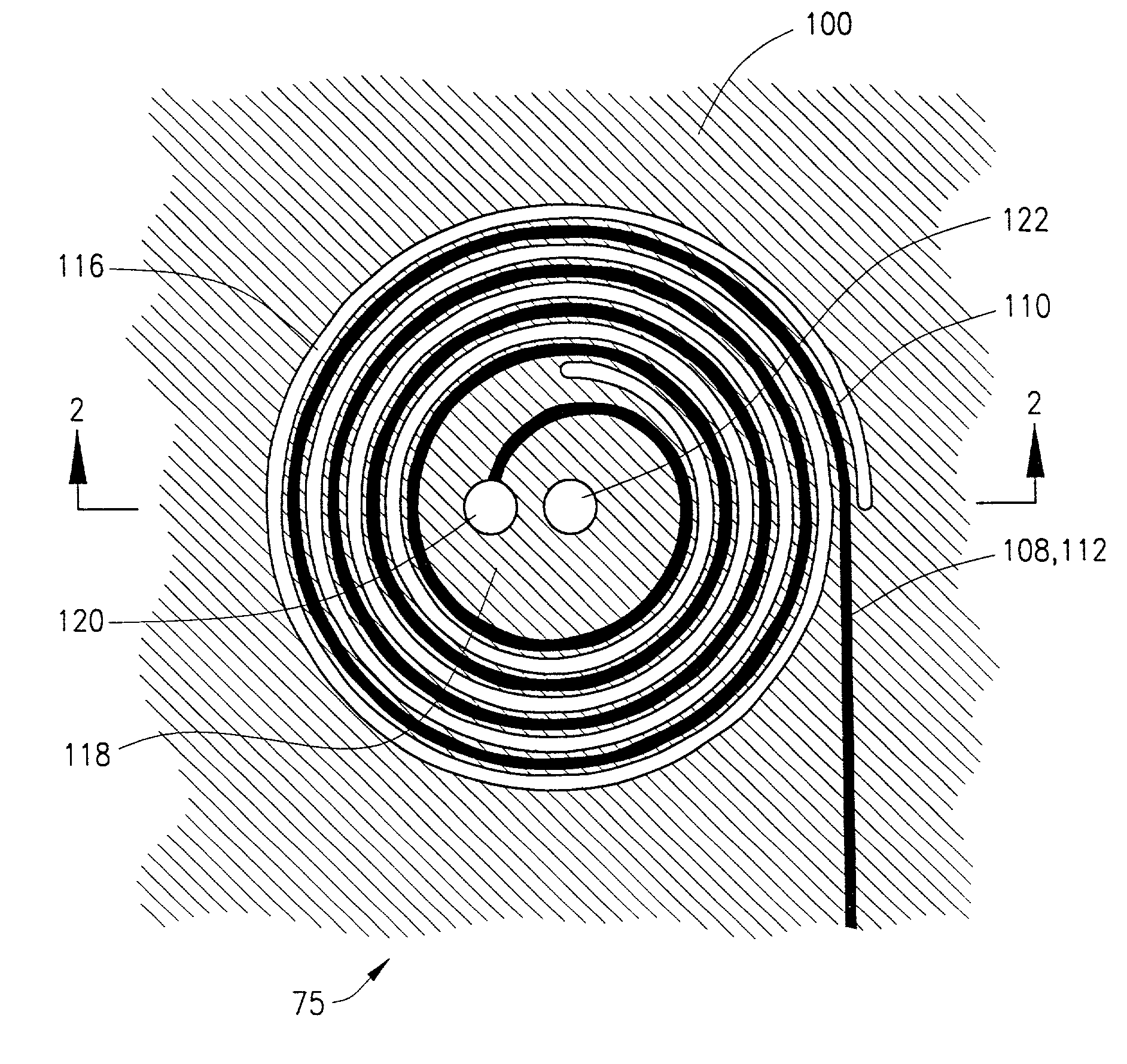
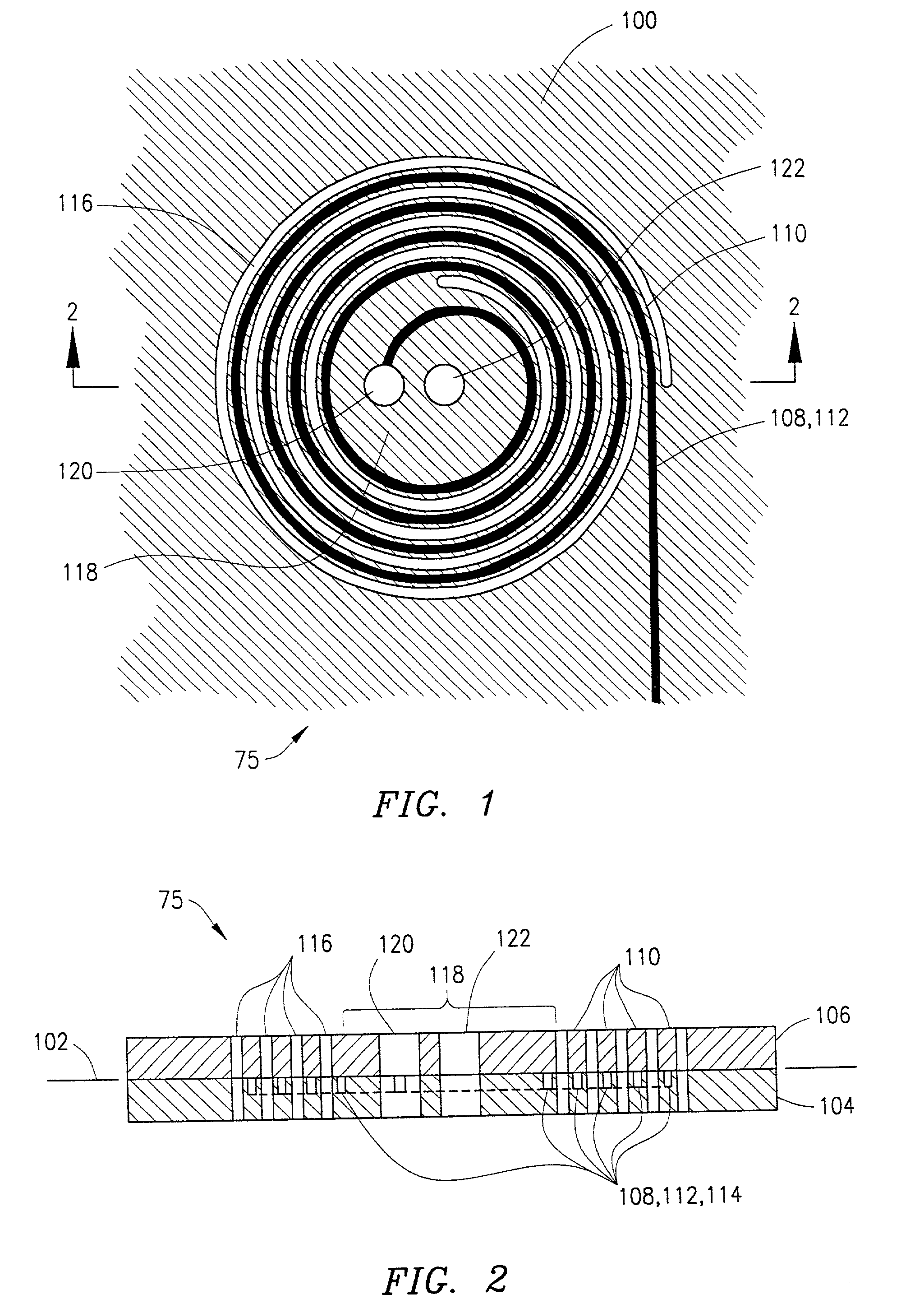
[0028] Referring now to FIGS. 1 and 2, an exemplary flex circuit 75 is shown. Flex circuit 75 has a flex circuit substrate 100 that defines a plane 102 (visible in FIG. 2). Substrate 100 is formed from a base sheet 104 (FIG. 2) and a cover sheet 106 (FIG. 2). Base sheet 104 is a flat sheet of polyimide, e.g., a DuPont Kapton.RTM. H sheet. It is understood that various other materials can be used, such as paper, polyamide, polyester terephthalate (PET), random-fiber aramid (Nomex), and polyvinyl chloride (PVC). Metal foils and sheets can also be used either separately from electrical insulators where electrical insulation is not required or in conjunction with electrical insulators to provide improved structural characteristics. Base sheet 104 is about 50 .mu.m (micrometers) thick, but can have a thickness in a range of about 25 .mu.m (micrometers) to 1 mm. Cover sheet 106 is laminated to base sheet 104 to form substrate 100. Cover sheet 106 is a sheet of, e.g., DuPont Kapton.RTM. HK...


PUM


Abstract

A planar extensible structure in a flat planar flex circuit can be extended out of the plane of the circuit by a distance of more than the width of the structure to carry fluids, electrical signals or optical signals into and out of the circuit. The planar extensible structure may be an Archimedes spiral, a parabolic spiral, a polygonal spiral, a non-spiral extensible shape, or other extensible shape. The invention can be used to siphon fluid samples from each well in a multiple-well microtiter plate into a microfluidic manifold for utility in chemical and biochemical analysis. The invention can also be used to allow electrical interconnect between adjacent circuits or circuit boards, and can allow signals carried in optical fibers to be transferred between optical circuits in different planes.

Description

[0001] 1. Field of the Invention[0002] The present invention relates to fluidic, electrical, electronic, and optical flex circuits and connections thereto.[0003] 2. Background of the Invention[0004] Flex circuits, also known as flexible circuits, flexible printed circuit boards, and flexible printed wiring, are circuits made in or on flexible substrates, which substrates are substantially planar in shape. The flexible substrates may be bent and folded in order to accommodate three-dimensional shape requirements.[0005] Flex circuits were first described by Albert Hanson of Berlin, Germany in British Patent 4,681 issued in 1903. The patent is noted in "Flexible Circuitry--Technology Background and Important Fundamental Issues"by Joseph Fjelstad, available on the internet at http: / / www.tessera.com / library.cfm, which article also provides a good overview of electrical flex circuit technologies. Further overview material on flex circuits is provided by the same author, Joseph C.Fjelstad,...

Claims


Application Information

Patent Timeline
IPC IPC(8): G02B6/125G02B6/13G02B6/44H05K1/11
CPCG02B6/125H05K1/118G02B6/4453G02B6/13Y10T137/86348
Inventor BARTH, PHILLIP W.KILLEEN, KEVIN
Owner AGILENT TECH INC
Why Eureka
Try Eureka