Fuel injection valve for internal combustion engines, and a method for producing same

a technology for internal combustion engines and fuel injection valves, which is applied in the direction of fuel injection pumps, stress reducing fuel injection, machines/engines, etc., can solve the problems of not being able to go below the limit, the wall of the inlet conduit cannot drop, and the limit of making the valve retaining body any slenderer or increasing the fuel pressur

Inactive Publication Date: 2003-04-17
ROBERT BOSCH GMBH
View PDF6 Cites 3 Cited by
  • Summary
  • Abstract
  • Description
  • Claims
  • Application Information

AI Technical Summary

Benefits of technology

[0003] The fuel injection valve of the invention having the definitive characteristics of claim 1 has the advantage over the prior art that the inlet conduit in cross section has an oval or elliptical shape, and the greatest length points in the circumferential direction of the valve body part. As a result, the wall region between the hollow chamber and the inlet conduit, or between the inlet conduit and the outer wall face of the valve body part, is larger without there being a need to reduce the cross-sectional area of the inlet conduit. As a result, for the same outside dimensions of the valve body part and the same embodiment of the hollow chamber, a higher fuel pressure in the inlet conduit of the valve body part can be achieved. Alternatively, provision can be also made to give the valve body part a slenderer design, and to leave the fuel pressure in the inlet conduit unchanged.[0004] An inlet conduit of oval cross section offers the advantage over a circular cross section that because of the greater wall thickness between the inlet conduit and the hollow chamber, or between the inlet conduit and the outer jacket face of the valve body part, greater tolerance in the manufacture of the valve body part is permissible, without any loss of stability to resist the high fuel pressure in the inlet conduit. As a result, the valve body part can be produced at less effort and thus less expense.[0005] In an advantageous method for producing the fuel injection valve of the invention, a circular bore is made eccentrically in a cylindrical body, which solid and preferably is of metal, the bore being parallel to the longitudinal axis of this body. The cylindrical body has an outer diameter that is greater than the desired outer diameter of the valve body part. By plastic deformation of the cylindrical body, the desired outer diameter is achieved while maintaining the cylindrical shape of the outer jacket face; the cross section of the inlet conduit is deformed and assumes an oval or elliptical shape. Only after this method step is the hollow chamber formed, so that the inlet conduit extends within the wall of the hollow chamber. By means of this method it is advantageously possible to produce an inlet conduit of oval or approximately elliptical cross section, without embodying such an inlet conduit directly in the valve body part, such as by drilling or milling, which would be complicated and hence expensive.

Problems solved by technology

The result, in the known fuel injection valves, is the disadvantage that if the valve retaining body has a slender design, the wall of the inlet conduit must not drop below a certain wall thickness, if it is to be able to withstand the fuel pressure.
Hence there is a limit to making the valve retaining body any slenderer or increasing the fuel pressure in the inlet conduit, and with the construction known thus far it has not been possible to go below this limit.

Method used


Image

  • Fuel injection valve for internal combustion engines, and a method for producing same
  • Fuel injection valve for internal combustion engines, and a method for producing same

Examples


Embodiment Construction

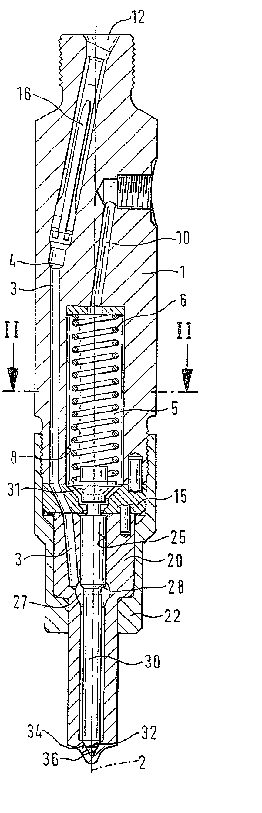
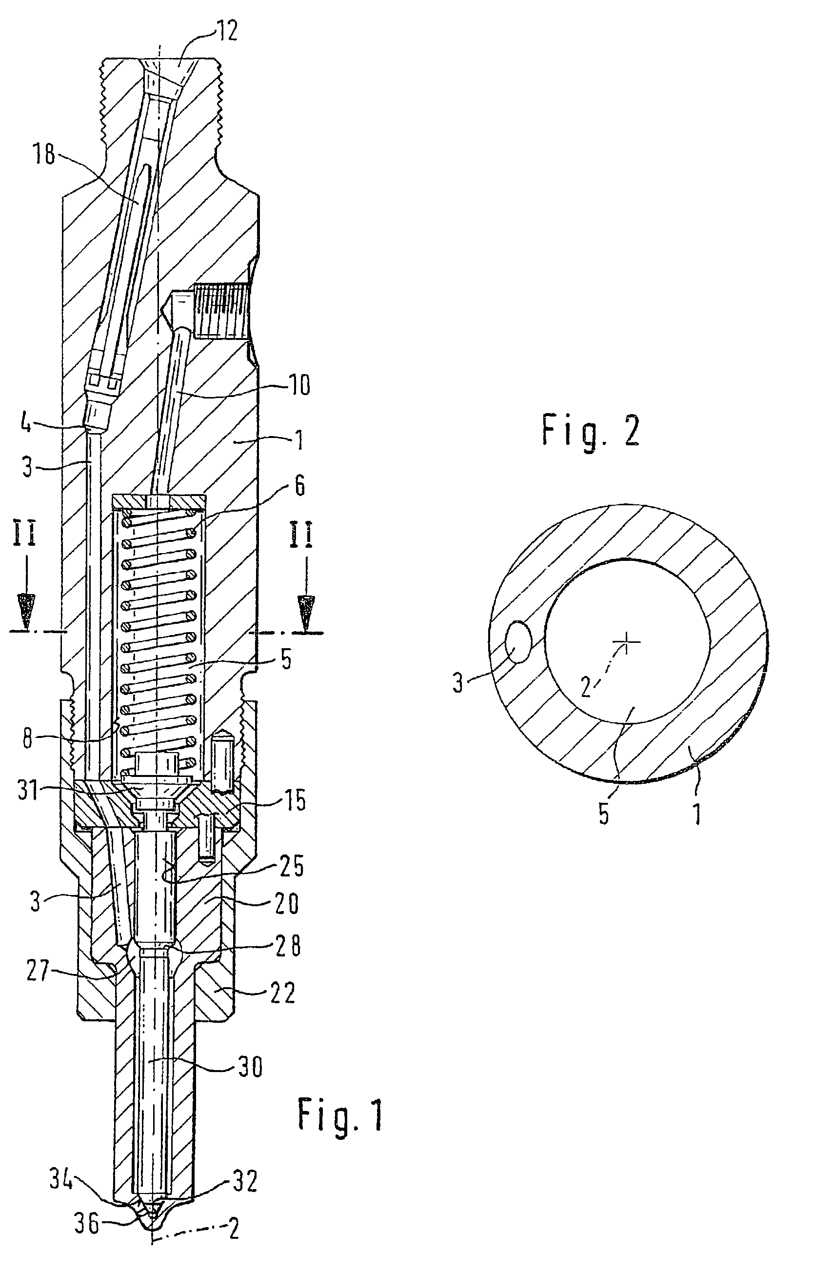
[0007] In FIG. 1, a longitudinal section through a fuel injection valve of the invention is shown. The fuel injection valve has a valve body 20, which is braced with a tightening nut 22, with the interposition of a shim 15, against a valve body part embodied as a valve retaining body 1. In the valve body 20, a bore 25 is embodied as a blind bore, and on its end toward the combustion chamber, there is a substantially conical valve seat 32, in which at least one injection opening 36 is disposed. A pistonlike valve member 30 is disposed in the bore 25; the valve member is guided in the bore 25 in a portion remote from the combustion chamber and narrows, forming a pressure shoulder 28, toward the combustion chamber. On the end toward the combustion chamber of the valve member 30, a substantially conical valve sealing face 34 is formed, which cooperates with the valve seat 32 to control the at least one injection opening 36. The pressure shoulder 28 is disposed in a pressure chamber 27 e...


PUM

PropertyMeasurementUnit
pressureaaaaaaaaaa
lengthaaaaaaaaaa
diameteraaaaaaaaaa

Abstract

A fuel injection valve having a valve retaining body (1), which has a longitudinal axis (2) and in which a central spring chamber (5) is embodied. In this spring chamber (5), a closing spring (6) is disposed, which transmits a closing force to a valve member (30), which valve member (30) cooperates with a valve seat (32) for controlling at least one injection opening (36). In the wall of the spring chamber (5), an inlet conduit (3) extends parallel to the longitudinal axis (2) of the valve retaining body (1), and by way of this conduit, fuel at high pressure can be delivered to the at least one injection opening (36). The cross section of the inlet conduit (3) has a greater length in the circumferential direction than in the radial direction, so that the wall region between the inlet conduit (3) and the spring chamber (5), or the outer jacket face of the valve retaining body (1), is larger than in the case of an inlet conduit (3) with the same size of cross-sectional area and a circular cross-sectional contour (FIG. 1).

Description

PRIOR ART[0001] The invention is based on a fuel injection valve for internal combustion engines as generically defined by the preamble to claim 1. In one such fuel injection valve, known from German Published, Nonexamined Patent Application DE 196 08 575 A1, a valve body is axially braced against a valve retaining body with a tightening nut, with the interposition of a shim. In the valve body, a bore is embodied, in which a pistonlike valve member is disposed that is axially movable counter to a closing force. On the end of the valve member toward the combustion chamber, a valve sealing face is embodied on the valve member; this face cooperates with a valve seat embodied on the end toward the combustion chamber of the bore, so that the valve member, as a result of an opening stroke motion counter to a closing force, opens at least one injection opening. An inlet bore is embodied in the valve retaining body, shim and valve body, and through this bore fuel at high pressure reaches as...

Claims


Application Information

Patent Timeline
Patent Type & Authority Applications(United States)
IPC IPC(8): B21H1/00B23P15/16F02M61/16F02M61/18F02M61/10
CPCB21H1/00B23P15/16F02M55/008F02M2200/03F02M61/18F02M61/184F02M61/168F02M2200/8015
Inventor KULOVITS, WALTERGOTTSCHLING, JUERGEN
Owner ROBERT BOSCH GMBH
Why Eureka
Try Eureka